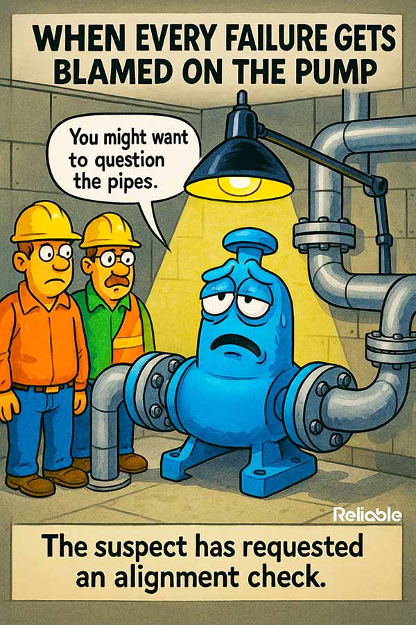

A pump that keeps landing on the repair bench looks guilty. It gets pulled, rebuilt, and set back on its base, and a few months later it returns with the same wear pattern in the same places. Learning how to prevent centrifugal pump failure starts with a harder question than which part broke: what in the surrounding system keeps pushing this machine past the point where its bearings and seals can survive?
The pump earns suspicion because it is the part that visibly breaks. A bearing grinds, a seal weeps, a coupling frets, and the work order names the component that failed. The casing and impeller, though, often answer to forces that arrive through the piping, the foundation, and the daily operating decisions made far from the pump room.
That reframing matters because it changes what a repair is for. A rebuild that only restores the broken part sends a healthy machine straight back into the same punishing conditions. A rebuild paired with a look at the installation gives the plant a chance to break the cycle for good.
Why the Pump Usually Gets Blamed First
Repair history tells a one-sided story. The log records what was replaced and rarely captures why the part gave out. Over a few years, a stack of bearing and seal changes builds a quiet case against the pump and closes the file on everything sitting upstream of it.
A broken bearing is easy to photograph, easy to log, and satisfying to replace. The source of the trouble tends to be harder to see, because it lives in pipe loads, soft feet, and flow conditions that leave few marks a camera can capture on the shop bench.
A repair record that only ever names the pump is a sign the investigation stopped at the easiest part to reach.
When the same failure mode returns on a predictable cadence, the pattern itself becomes data. It suggests the rebuild may be restoring the symptom without removing whatever keeps recreating the damage.
Treating that cadence as ordinary wear keeps the plant on a rebuild treadmill. The parts get better, the machinist gets faster, and the underlying load stays exactly where it was, waiting for the next set of components to absorb it.
Reading the System Around the Casing
Prevention gets easier once the pump is treated as a reporter of system conditions rather than automatically assumed to be their origin. A focused walk-down can surface likely contributors quickly. Begin with the parts of the installation that can transmit force into the casing or disturb the pump hydraulically.
- Pipe strain from unsupported spools or thermal growth that pulls the casing out of position
- Coupling misalignment that can increase bearing and seal loads
- Soft foot and a distorted baseplate that twist the pump as the hold-down bolts are pulled tight
- Suction conditions that reduce NPSH margin or disturb inlet flow, increasing cavitation risk
Each of these arrives from outside the pump and then shows up inside it. The bearing and the seal simply keep the running tally of forces the rest of the system sends their way.
Alignment sits near the top of the list for good reason. Cold alignment alone does not describe where the shafts will sit in operation: thermal growth, base movement, and piping loads can change relative shaft position after startup. Where those effects are significant, disciplined shaft alignment work should use the machine’s specified target offsets and installation tolerances rather than a generic ‘few thousandths’ rule.
Pipe strain deserves the same suspicion as a worn coupling. During a properly isolated and depressurized outage, check for pipe-induced movement and flange misalignment using the plant’s approved procedure. Visible movement as connections are released can indicate that the pump nozzles have been carrying piping loads that should be corrected.
How to Prevent Centrifugal Pump Failure Upstream of the Casing
The upstream fixes are less celebrated than a fresh rebuild, and they can last much longer. Adding a pipe support, correcting a spring hanger, or re-shimming a soft foot can remove a system load that a bearing upgrade does not address.
Field alignment deserves the same care as the rebuild itself. Check for pipe-induced movement and soft foot, then align the shafts to the specified cold target, including any approved offset for expected thermal growth. That helps keep transmitted loads within the range the machine was designed to tolerate.
Spend time verifying alignment and pipe strain before blaming the rebuilt pump again. When installation forces are the driver, correcting them is what breaks the repeat-repair cycle.
Vibration data gives the upstream story a voice on the floor. Running-speed vibration and harmonics can be consistent with misalignment, looseness, unbalance, or other faults, so the spectrum should be treated as evidence rather than a one-pattern diagnosis. Working through the common centrifugal pump vibration causes alongside phase, waveform, operating condition, and inspection findings turns a vague complaint into a more defensible work list.
The aim of each fix stays the same. Shrink the forces the casing has to absorb, and the wear parts get to age on their own schedule instead of on a schedule the piping dictates for them.
Suction Conditions and the Operating Point
Force is one half of the story, and flow is the other. Operating well outside the pump’s preferred operating region can promote recirculation and flow separation, increase hydraulic loading and vibration, and raise the risk of cavitation.
- Available NPSH with too little margin above the pump’s required NPSH for the actual service and operating point
- Excessive throttling or loss of minimum-flow recirculation that drives the pump below its permitted low-flow range
- Clogged strainers and collapsing suction hoses that quietly starve the inlet
- Frequent low-flow operation that can raise liquid temperature, hydraulic loading, vibration, and shaft deflection
These conditions leave clues, but few are unique to one cause. Cavitation can produce characteristic pitting or erosion, while sustained low-flow operation can show up as abnormal temperature, vibration, recirculation damage, or unstable performance. Confirm the diagnosis with operating data and the pump manufacturer’s guidance rather than relying on one wear pattern alone.
Matching the pump to how the process actually runs, whether through an impeller trim, a different pump selection, or variable speed control, can move the normal operating point closer to the pump’s preferred region when the engineering supports the change.
Operators hold part of this fix in their hands. A pump held at very low flow to maintain a downstream setpoint may be operating below its recommended range, so confirming the manufacturer’s minimum-flow requirement can do more for reliability than another round of premium replacement parts.
Turning Repairs Into Root-Cause Fixes
A durable prevention habit closes the loop between the repair bench and the field. Every rebuild becomes a chance to ask what sent this part here and to record the answer somewhere the next planner will actually read it.
That habit borrows directly from failure investigation. Even a focused root cause failure analysis on a repeat pump can connect the failed component to installation, hydraulic, operating, or maintenance contributors and turn repair history into corrective action.
The cheapest pump repair is the one the system stops requiring, and patient root-cause work is how a plant earns it.
Prevention, in the end, is a shift in where the plant points its attention. The pump keeps reporting the truth about its installation, and a team that reads the whole system gets far more life out of every machine on the floor.
Start with the next repeat offender on the list. Walk its piping, check its feet, verify cold alignment against the specified target, review suction conditions and operating flow, and then use the next months of condition and repair data to see whether the corrective work is holding.