
The first gearbox was condemned for excessive gear mesh backlash. A borescope inspection of its replacement found a very different problem waiting inside.
| Equipment | Replacement gearbox for a ball mill: pinion, ring gear, and support bearings |
|---|---|
| Background | The original gearbox was condemned for excessive gear mesh backlash, a pinion-related fault |
| Inspection | On-site borescope inspection of the replacement, through the gearbox inspection window |
| Key findings | Moisture-driven oxidation and standstill marks from prolonged inactivity, plus early load marks |
| Recommendation | Internal cleaning and a preservation plan before the unit is accepted for service |
One ball mill, two gearboxes
This ball mill had already lost one gearbox. The original unit was condemned after vibration analysis flagged excessive gear mesh backlash, a clear sign of a pinion-related fault. The plant sourced a replacement, and the original gearbox came out.
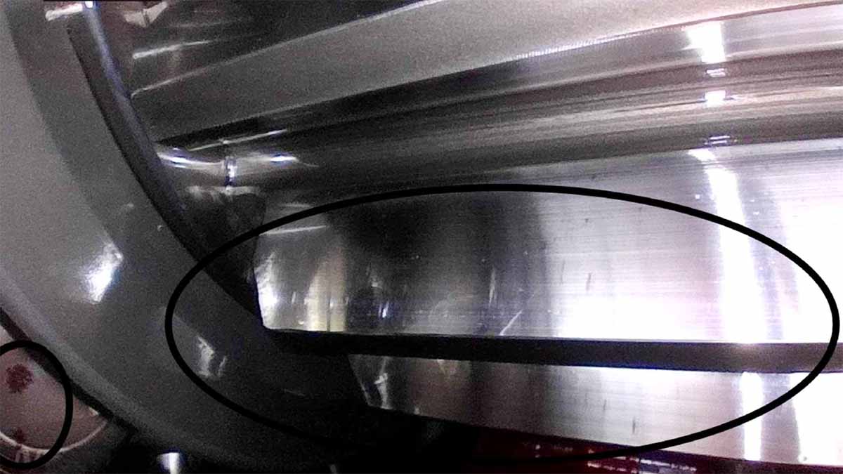
That should have been the end of the story. Before the replacement was accepted for service, an on-site evaluation was carried out to confirm its condition. A borescope was passed through the gearbox inspection window to check the pinion, the ring gear, and the bearings.
Even without a stroboscope to freeze the gears, the camera picked up surface marks straight away. The replacement was not in the clean condition its role implied. Several areas on the gear teeth and the rolling elements showed discoloration, some of it obvious, some ambiguous enough to note for closer review. This is what the inspection found.
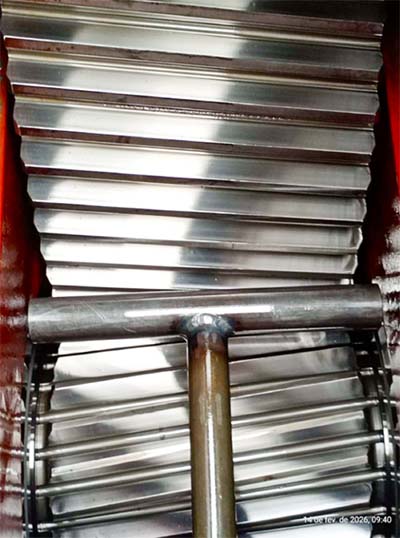
Figure 1. The replacement gearbox: pinion and ring gear teeth, seen through the inspection window.
Oxidation or paint?
The first question was whether the reddish areas were corrosion or simply paint. It matters, because the two point to very different stories.
The internal surfaces of a gearbox like this are normally coated with a high-resistance epoxy primer. When that coating fails, it tends to behave in a predictable way. It either exposes bright, shiny metal underneath or lifts off in well-defined solid flakes. Neither pattern matched what the borescope showed here.
The visual character of the marks pointed instead toward corrosion. The recommended way to confirm it is to check the surface texture directly. A porous, irregular surface is a strong sign of active rust.
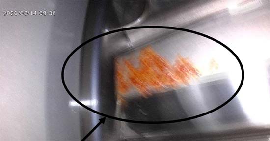
Figure 2. A large oxidation mark spread across the contact face of a gear tooth.
Standstill marks on the gear teeth
The teeth carry a specific and recognizable pattern: standstill marks. These show up as vertical bands of oxidation that trace the exact contact profile of the meshing teeth.
The pattern is really a record of time. When a gearbox sits in the same position for a long stretch, internal humidity condenses on the metal surfaces that are not submerged in oil. That moisture collects along the contact line between meshing teeth, where the lubricating film is thinnest or absent. Over weeks or months, it drives a chemical oxidation of the steel itself.
The mark follows the grain of the metal. That is the signature of corrosion attacking the surface, the chemistry of a gearbox left standing.
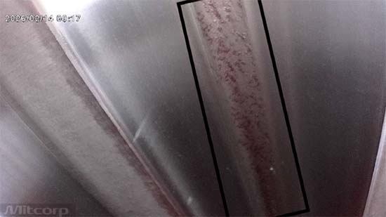
Figure 3. Vertical oxidation banding on a gear flank, tracing the tooth contact line. A classic standstill mark.
A spare gearbox is only as reliable as the way it was preserved.
Longitudinal marks on the teeth
A second set of marks runs in the direction of gear movement. These longitudinal lines have a different origin from the standstill banding.
Marks like these usually mean something abrasive has been working between the teeth and the races. The likely candidates are small dirt particles, metallic debris, or contact loads that exceeded what the material was built to carry. A material quality evaluation is worth doing here to confirm or rule out the overload explanation.
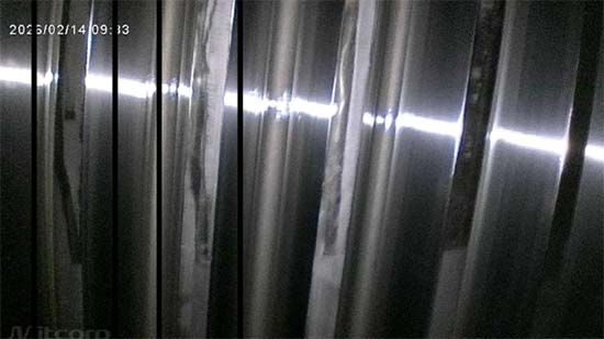
Figure 4. Longitudinal scoring running in the direction of gear movement.
Dark transverse lines and early micropitting
The dark transverse lines on the gears are sharp and well-defined, and that definition is the clue. A mark this clean forms when the teeth are pressed hard against each other while stationary, holding static contact for a long period.
There are also early indications of micropitting. This is the stage where microscopic fragments of material begin to detach from the surface under contact stress. Those fragments do not simply disappear. They can accumulate inside the housing, which may help explain the deposits found elsewhere in the gearbox.
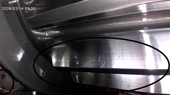
Figure 5. A dark, sharply defined transverse line on the gear teeth, with particle accumulation visible at lower left.

gure 6. Fine surface marks and early micropitting indications on a tooth flank.
Corrosion on the bearings
The rolling elements tell a similar story to the gears. Reddish stains across several of them point to corrosion that set in while the gearbox was stationary.
There is a second mechanism worth flagging. When a gearbox sits idle but is exposed to outside vibration, from nearby running equipment for example, the rollers can take repeated micro-impacts against the races. This is false brinelling. Each tiny impact breaks the lubricating film and exposes fresh metal, and that metal then oxidizes. The result is localized corrosion in a gearbox that never ran hard enough to wear it.
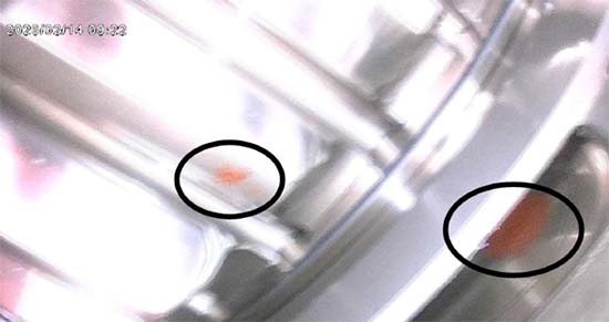
Figure 7. Reddish corrosion staining on the bearing rolling elements.
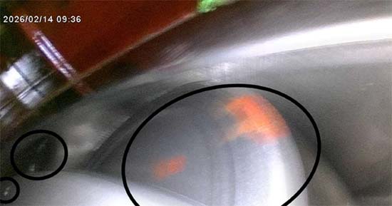
Figure 8. Further corrosion marks across the rolling elements and races.
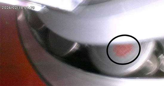
Figure 9. A localized red corrosion stain on a single rolling element.
Particle deposits
One frame showed an accumulation of particulate material inside the housing. Its origin has not been confirmed, and a laboratory analysis would settle it. If those particles turn out to be metallic wear debris, they become a problem of their own.
Loose metallic particles act as an abrasive. Once the gearbox is running, that material circulates between the gears and bearings and accelerates wear. The dark gray coloration seen on some of the teeth may already be a sign of that process getting underway.
What the inspection points to
The borescope inspection points to one dominant theme. The replacement gearbox shows clear signs of moisture contamination and oxidation, driven by a prolonged period of inactivity in a stationary position. Layered on top of that are early load and contact marks worth evaluating before the unit runs.
The most likely root cause is water in the oil, or internal condensation during the time the gearbox sat idle. Either one drives chemical attack on the metal wherever the lubricating film was broken or absent. The standstill marks on the teeth and the corrosion on the bearings both fit that explanation.
The damage here is a story of time and moisture. The gearbox sat still long enough, in conditions humid enough, for corrosion to take hold. The borescope caught it before the replacement was accepted for service. In its current condition the unit was rejected, pending internal cleaning and a proper preservation regime.
Recommended actions
Two priorities come out of this inspection.
- Clean the gearbox internally. Remove the accumulated particles and corrosion products before the unit is commissioned. Once the gearbox is running, loose debris circulates and abrades gear and bearing surfaces.
- Put a preservation and hibernation plan in place. This applies to the inspected unit and to any spare gearbox held in reserve. A workable plan should cover:
- Humidity control inside the housing
- Protection of the internal metal surfaces
- Periodic rotation of the assembly so the same teeth are not always in contact
- Isolation from external vibration sources
- Scheduled visual inspections
- A defined return-to-service procedure
Condemning the first gearbox was the straightforward call. The harder lesson sat in the replacement. A spare is only as good as the way it was kept, and this one had been quietly corroding while it waited. A borescope and an existing inspection window caught it before the ball mill inherited a second gearbox problem.