
A 55 MVA, 13.8 kV steam turbine generator presented a persistent and costly problem: repeated instantaneous overcurrent (IOC) trips during excitation. The trips occurred over time, at first, then immediately upon excitation or within minutes, preventing reliable synchronization and operation.
Over several years, multiple corrective actions were attempted by motor repair, consultants, the OEM, and others. Control components were replaced, the rotor was balanced, and standard electrical testing was performed. Yet the problem continued and gradually worsened, taking the site completely offline.
Vendors were found using LLMs to try to solve the problem without reviewing standards, methods, and industry procedures due to limited experience. Something we’ve fondly referred to as ‘vibe consulting’ (as opposed to vibration consulting).
If a fault cannot be found, the issue may not be the machine. It may be the method used to evaluate it.
The central question remained unsolved: was the issue in the excitation system – or inside the generator itself? When we arrived, everyone had them performing unusual testing on the excitation system, yet the symptoms didn’t support an excitation circuit defect.
Traditional troubleshooting focused on the most likely causes: excitation controls, AVR instability, and mechanical vibration. Earlier standard electrical tests reported acceptable insulation resistance and no obvious catastrophic defects, except for insulation migration and the ejection of an insulation block. For some unfathomable reason, a repair shop told the client this was not a problem and balanced the loss of material.
However, the failure mechanism existed outside the capability of these methods: it was intermittent, voltage-dependent, and dynamic, appearing only under excitation conditions. In short, the problem could not be identified using static or isolated testing alone.
When the Usual Fixes Keep Failing, the Method Is the Problem
MotorDoc approached the problem differently after having the history and problems described. We immediately suspected a rotor defect and explained that the ejection of insulation blocking is a catastrophic defect. However, the trip did not follow the pattern of an end-of-turn short.
The original plan was to perform an assembled run test, but one of the vendors, who was unable to determine the fault, had the equipment disassembled and then attempted to direct the analysis. We informed the vendor that they were not competent enough to direct the analysis and implemented an altered version of our test plan.
- EMPATH ESA: would have identified the defect immediately. The vendor explained that vibration was unable to detect the problem. We stated: ‘Of course it didn’t, this isn’t a vibration problem.’ Instead, the purpose was to see what happened electrically, at which point we had to have them removed for calling out testing the rotor with ESA, rather than the proper use of ESA, which requires testing from the stator. This happened the next week, after we had the client reassemble the machine, delaying the prognosis by over a week. Lesson: Listen to the experts, not those who couldn’t determine the issue in the first place.
- ALL-TEST Pro 7: For low-voltage circuit evaluation, which was critically important to identify the severity of the issue. Motor Circuit Analysis (MCA) is referred to as ‘low voltage testing’ due to the output of the instrument, not the size or rating of the machine. We used this well before applying high voltage testing to avoid having to explain to clients that the machine that we destroyed with high voltage testing methods in the field failed, because we found the defect.’ This often occurs with insulation system defects that can be mitigated, such as clean, dip, and bake, instead of the rather expensive rewind.
- Electrom High Voltage Tester: with low voltage testing, partial discharge surge testing, and higher voltage testing, but well below the rating of the machine. The system we used was an 11kV High Output solely to determine any obvious issues. This selection was due to how quickly the Electrom trips when a defect is detected, reducing the problem of failing a winding that could otherwise be corrected.
Each test method contributed to the puzzle and, together, identified the fault(s).
Three Tools, One Machine, and a Fault Nobody Else Could Find
Offline testing began with the ALL-TEST Pro 7, evaluating resistance, impedance, inductance, phase angle, and contamination indicators. The results were subtle but significant: the rotor exhibited non-repeatability and measurable contamination levels, with the stator showing only minor unbalance.
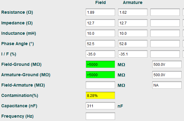
Figure 1: Closest ATPro7 rotor tests results showing non-repeatability and contamination indicators.
In electric machine insulation systems, repeatability is a key indicator of health. Variations between repeated measurements suggest instability within the winding system, often associated with insulation degradation, contamination, or developing turn faults. This was a clear indicator that the rotor was in poor condition.
Electrom testing was then used to evaluate insulation performance under increasing electrical stress. Initial low-voltage tests showed acceptable insulation resistance and only minor capacitance imbalance in the stator.
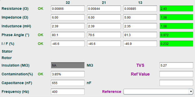
Figure 2: Low voltage test results showing minor unbalance, conditions that appear acceptable under standard testing but can mask developing defects.
However, when high potential (Hipot) testing was performed, the results changed dramatically. The test was set to approach 10kV DC but tripped very early due to overcurrent, indicating rapid leakage current rise.
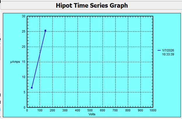
Figure 3: hipot test showing rapid rise in leakage current and early trip, clear evidence of insulation weakness under voltage stress.
Surge testing further confirmed the issue. The test could not reach the intended voltage, preventing waveform comparison and indicating compromised insulation integrity.
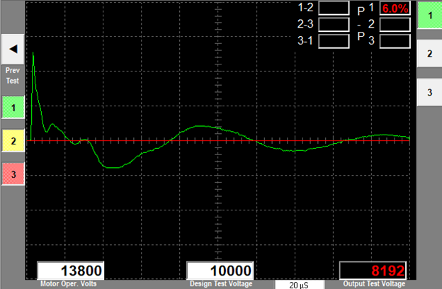
Figure 4: Surge comparison test aborted below target voltage, indicating some form of degraded winding insulation
At this stage, the evidence demonstrated a critical point: the insulation system appeared acceptable at low voltage but failed under high-stress testing. This points us toward a lead condition or a winding compromise. The operating description indicates it is more likely a lead condition.
What the Machine Revealed Once It Was Actually Running
After the generator connections were re-made and the steam systems were lined up, plans were made to operate the generator on battery power to the exciter, as AC power caused an instantaneous trip. We only required the machine to be under excitation for a few minutes for EMPATH ESA testing. This would help determine if the issue originated in the rotor or the excitation system.
Measurements were taken using CTs and PTs from the excitation system, allowing safe observation of voltage and current behavior during operation.
When excitation was applied, the generator exhibited sustained oscillations in both voltage and current. These oscillations increased prior to synchronization and did not damp as expected once excitation current was applied.
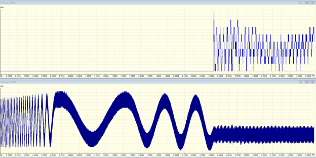
Figure 5: Voltage and current oscillations during excitation, indicative of rotor instability rather than control system response. Current top and voltage bottom.
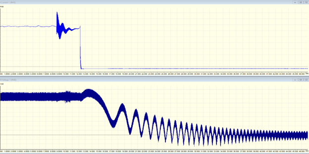
Figure 6: Voltage and current oscillations and trip.
Analysis showed oscillation frequencies around 1.25 Hz, matching theoretical rotor dynamic behavior. This confirmed that the oscillations were inherent to the machine and not caused by control instability.
Further spectral analysis revealed strong second harmonic components in both voltage and current, widely recognized as a signature of rotor winding asymmetry or turn-to-turn shorts.

Figure 7: Voltage and current harmonic spectra showing strong second harmonic content, diagnostic of rotor winding faults.
Additional ESA data, when the system tripped within four minutes, identified rotor slot pass frequencies, stator slot interactions, and mixed eccentricity patterns, all indicating rotor field unbalance and air gap distortion.
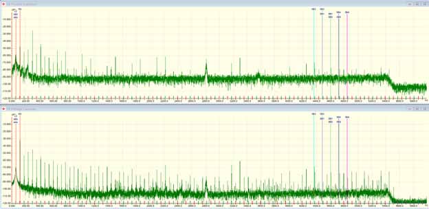
Figure 8: ESA spectra showing eccentricity and slot-pass frequencies, evidence of rotor field unbalance and mechanical interaction.
By combining the results of the ATPro7, which identified early rotor instability, Electrom testing, confirmed insulation weakness under stress, and EMPATH ESA verification of rotor-related dynamic faults, the conclusion was clear: The generator rotor had insulation failure and electrical unbalance from turn-to-turn shorts and eccentricity.
The recommendation was to remove the rotor to determine the extent of the damage for potential cleaning versus rewind. The generator was disassembled as soon as a service company was available.
Contamination, Shorts, and What the Rotor Confirmed
Following disassembly, MotorDoc evaluated the physical condition of the rotor along with a company that specializes in turbo-rotor repairs, confirming the prognostic results.
Inspection revealed:
- Severe metallic and organic contamination throughout the rotor.
- Contamination embedded within the insulation system.
- Evidence of insulation degradation and electrical tracking.
- Outer rotor coils exhibiting electrical shorting.
- Rotor ground protection devices were destroyed.
Insulation resistance dropped significantly after exposure, confirming that contamination was actively contributing to electrical conduction paths.
The contamination source was traced to environmental ingress, likely through compromised filtration and structure, allowing debris, including metallic particles, to enter the rotor system. Samples of the material were sent out to confirm the makeup of the material, as no direct source could be confirmed.
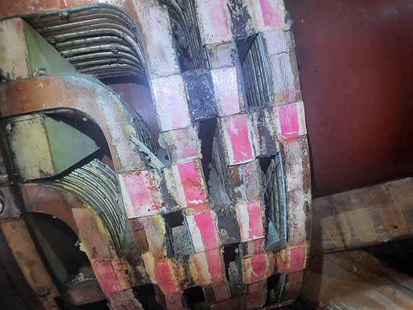
Figure 9: Rotor contamination.
Previous troubleshooting efforts failed not because of a lack of effort, but because of limited diagnostic scope, ignoring testing and troubleshooting standards, and a lack of experience.
- Mechanical balancing reduced symptoms but did not address insulation damage and the actual cause.
- Control system replacement addressed assumed causes, not actual ones.
- Standard testing did not apply sufficient electrical stress or dynamic analysis.
- In many cases, indications were found with prior testing, but were either ignored due to fault bias or inexperience and lack of knowledge in insulation testing. Fault bias is when a fault is predetermined, and all data that refutes that assumption is ignored.
This case demonstrates how large rotating equipment must be evaluated, and one of the reasons why standards organizations are spending more resources in explaining why tests are performed. Additionally, the following are specific to this study:
- Static testing alone is not enough: many insulation failures only appear under operating voltage conditions.
- Electrical and mechanical failures are often interconnected.
- Integrated diagnostics provide clarity: no single test identified the fault. The combination of tests and inspections, as well as simple root-cause steps.
If a fault cannot be found, the issue may not be the machine; it may be the method used to evaluate it. Referencing the latest versions of standards, utilizing expertise, and understanding machine operation are critical.
While it was revealed that several prior companies used LLMs to help troubleshoot, you must still have expertise in the technology, as the AI conclusions that generated the biases and used them to interpret the data were horrifically wrong. This caused further damage to the equipment, resulting in lost operations and extremely costly repairs.
In this case, the proper use of ESA and the proper selection of tools, as outlined in IEEE Standard 1415-2006, resulted in the correct analysis. IEEE P1415 is presently under revision to include additional root-cause processes and testing methods.
Finally, third parties who are unable to resolve the issue should NEVER be given a role in directing root-cause evaluation and testing. This will only ever make the problem worse. In most cases, if put in this position, MotorDoc leaves the site until the stakeholders are ready to resolve the issue.
IEEE Standards (latest editions): 43, 56, 95, P97, 522, 1068, 1415, 1799
CIGRE: A1.78; Technical Brochure 879 (Guideline on Testing of Turbo and Hydro Generators)
EASA: AR100, EASA Technical Manual