Predictive Maintenance Technologies and How to Choose Them

What Are Predictive Maintenance Technologies?
Predictive maintenance technologies are measurement and analysis tools that are used to assess the condition of equipment, to detect deterioration, and to support maintenance decisions. They use measurements (e.g. vibration, temperature, lubricant condition, performance) which can be used to establish the condition of the equipment and to investigate a developing problem in order to determine whether, when and how to intervene.
Three different questions are implicit in that definition. Detection is 'has it changed?' Diagnosis is 'why has it changed?' and prognosis is 'what's the likely trajectory of the condition?' A reading which answers the first of those doesn't necessarily answer the other two and doesn't establish remaining useful life.
This guide looks at vibration, thermography, ultrasound, oil analysis, electrical testing, process monitoring and a range of nondestructive tests (NDT). Sensors collect the data, the communications system gets it to where it needs to go and the software assists the people in interpreting it and in managing their work.
Condition-based maintenance and predictive maintenance aren't always used to mean the same thing. The terminology often overlaps in practice. ISO's guidance on condition monitoring is a general framework for setting up a condition monitoring program. The real question you have to answer is which condition are you going to monitor in order to make a useful decision about the asset you have in front of you.
Predictive Maintenance Technologies Compared
The seven families in Table A are how the methods described here are grouped. They are by no means an exhaustive list or a rigid taxonomy. DOE and PNNL's guidance on the application of maintenance technologies is a good place to start in terms of relating the measurements to the equipment. You can use the comparison to identify the candidates and then go on to check the particular failure mode and measurement requirements.
Table A Technology comparison
Technology | Suitable applications | Measured evidence | Important limitation |
|---|---|---|---|
Vibration analysis | Rotating machinery, including fans and pumps | Overall trends, waveforms, and frequency spectra | Sensor setup, speed, and load affect interpretation |
Infrared thermography | Electrical connections and mechanical heating | Surface temperature patterns and differences | Emissivity, reflections, access, and load matter |
Airborne and structure-borne ultrasound | Compressed-air leaks, steam traps, and bearings | High-frequency acoustic signals and trends | Interference, access, and operating context matter |
Oil and wear debris analysis | Gearboxes and other oil-lubricated equipment | Lubricant condition, contamination, and wear evidence | Sampling and selected tests determine coverage |
Motor current analysis and electrical testing | Motors, motor circuits, and electrical systems | Running electrical signatures or deenergized test results | Different tests address different failure concerns |
Process and performance monitoring | Pumps, compressors, and process equipment | Flow, pressure, temperature, power, and performance trends | Process changes can resemble equipment deterioration |
Nondestructive testing and thickness monitoring | Components susceptible to corrosion or cracking | Wall thickness or relevant flaw indications | Method must suit material, geometry, access, and damage |
Complementary methods look at different symptoms. So vibration data on a pump might lead to a mechanical investigation whereas the flow and pressure data would be used to establish the operating conditions. Agreement between the measurements can be a way of supporting an interpretation but disagreement is also something that should be looked at. There is no one method that is best for every asset and you only gain by adding instrumentation if the extra data answers a relevant question.
Seven Predictive Maintenance Technologies and Their Applications
Vibration Analysis
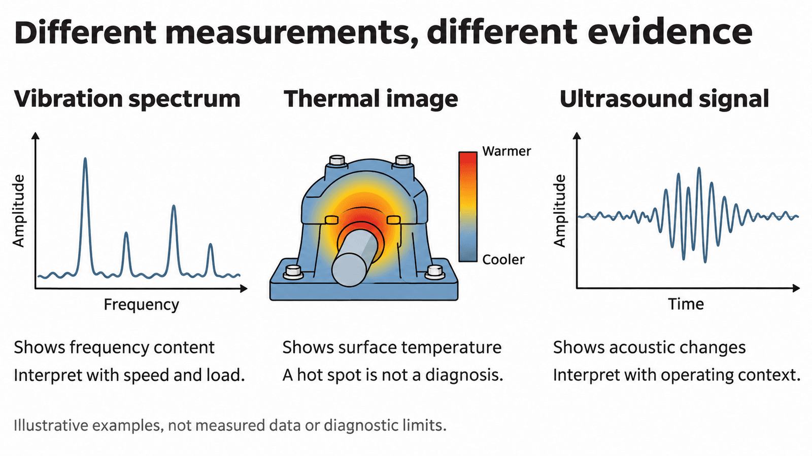
Vibration analysis is the measurement of mechanical motion and the examination of how that motion varies. It can be presented as an overall value (a single value summarizing vibration within a given measurement band), as a waveform (the signal over time) or as a spectrum (the frequency content separated out). All three of these are useful in the investigation of bearing damage, imbalance, misalignment, looseness and a host of other rotating equipment problems.
Think about an industrial fan with an increasing vibration trend. Before you go and have it balanced, check that the speed, the load and the measurement setup haven't changed. The analyst needs to look at the relevant diagnostic detail and the machine configuration before coming to any one diagnosis. A high overall reading is the trigger to look at the problem; it's not the diagnosis.
Specify repeatable sensor locations, orientations and mounting methods. Record the operating conditions with each collection so that the next reading can be properly compared. Reliable's guide to vibration analysis techniques and tools has further detail on the measurements used in these investigations.
During the tech selection process ask to see the data that the analyst would actually get as a result of an alert. Would they be able to see the waveform or the spectrum or is it just a status? You need to plan that follow-up access prior to relying on the vibration trend to authorize work.
Infrared Thermography
Infrared thermography is the estimation of surface temperature from the infrared radiation that is detected. The interpretation is in part a function of emissivity (the ability of a surface to emit radiation) and the radiation that is reflected from the surroundings. FLIR's article on emissivity and thermal imaging goes on to explain why the camera settings and the conditions under which you're viewing will have an effect on the temperature that you see. A camera doesn't see through an opaque housing.
An electrical connection that appears hotter than other similar connections needs to be looked at under known load. The image in itself doesn't prove you have a loose connection. You have to consider the possibility of differences in current, surface characteristics, cooling and reflections before deciding what the pattern is likely due to.
For a useful inspection you need to establish what surface you're looking at and have safe access to it. You need to record the load, the viewing location and the relevant environmental conditions with the image. The same applies when looking at heating on a piece of mechanical equipment. The surface pattern will give you the evidence but you still need to go on to establish the cause.
Qualified people must follow the applicable safe work practices during electrical thermography. A desire for an image is no excuse for uncontrolled exposure to energized parts. Ask the inspection company to explain how the observations will be verified and documented. If the evidence does in fact support the need for corrective work then you should retain the original image and records of the operating conditions so that a subsequent inspection can assess the outcome under comparable conditions.
Airborne and Structure Borne Ultrasound
Ultrasound instruments pick up acoustic energy in the range above that of normal human hearing. Airborne instruments pick it up as it travels through the air; contact probes pick it up as it travels through the structure of the equipment. Applications include the detection of compressed air leaks, the assessment of steam trap performance and the investigation of changes associated with bearing friction. These are to be distinguished from the applications of active ultrasonic thickness testing.
For example a technician looking at an air distribution line could use airborne ultrasound to locate a suspected leak. The finding would be the actual connection or component that needed looking at. The proximity of other ultrasound sources, obstructions, distance and system pressure will all have an effect on what you actually detect.
A contact measurement on a steam trap will of course require the trap type and operating cycle for context. The sound during normal discharge won't in itself be indicative of leakage. Temperature information and an appreciation of the trap's expected operation will be vital to the assessor in working out whether it's normal or not.
For bearing monitoring you need to establish consistent contact locations and instrument settings and record the speed and load. You then compare the trends to see if a change is significant enough to warrant a lubrication check or whether it's actually a case for further mechanical investigation. You don't automatically go in and make a grease addition the answer to every single louder reading.
Oil and Wear Debris Analysis
Oil analysis looks at three things: is the oil still good to use? Is there any contamination? Is there any evidence of wear which would point to a machine problem? The DOE and PNNL approach to lubricant and wear particle analysis is to split those three functions out and describe the tests that are used to achieve each. A single result won't characterize every wear mechanism or every particle size.
For an oil-lubricated gearbox you'd want to be selecting your tests around the questions that actually matter. Lubricant condition, water content and wear debris are all going to be different things and may all require different tests. Ask the lab what their proposed test package can detect, what it can't detect and what further analysis would be needed to resolve an ambiguous result.
Representative sampling is absolutely key. You need to establish a suitable sampling point and a consistent sampling procedure using clean equipment and properly labeled samples. The analyst will need the lubricant identity, service history, operating conditions and any records of oil additions, changes, filtration and any recent repairs as all of this will have an impact on how you interpret the report.
If a gearbox report comes back with a wear issue then look at the sampling history prior to deciding on an overhaul. A repeat sample, a complementary debris test or vibration evidence may well be the thing that actually settles the issue. You need to pick the right follow-up for the suspected mechanism. You also need to make sure that your routine oil sampling is appropriate for the asset in question. A grease-lubricated bearing with no oil reservoir is going to need a different initial measurement plan.
Motor Current Analysis and Electrical Testing
Motor Current Signature Analysis looks at the current signals as the motor is running. The frequency content can be used to help with the investigation of things like rotor-bar damage. Motor circuit and insulation tests on stopped, de-energized equipment look at other electrical characteristics. NASA's reliability-centered maintenance guide lists motor circuit analysis and motor current signature analysis as separate techniques.
For an induction motor driving some production equipment you start with the suspected failure. A running signature assessment and a de-energized insulation assessment will answer different questions. The purchase spec will state what test is required, what equipment state it's for and what the evidence from that test should be.
Record the supply and load conditions when you're looking at the running figures. Work out whether the variation is due to the motor, the load or the supply. Give the assessor the full operating history and the previous results and ask them what further evidence would be of value in determining which of those is responsible.
Qualified people must pick the right tests and carry out the appropriate electrical work practices (including the necessary de-energizing and verification procedures). You need to establish during the pilot that the required tests can be carried out safely at the required intervals and that the reports properly separate the observations from the diagnosis. You must not assume that a generic electrical health score is in any way a complete picture of the motor.
Process and Performance Monitoring
Process monitoring makes use of the measurements (flow, pressure, temperature, power etc.) to assess how the equipment is performing its function. The records can indicate a developing problem with performance but the significance of the records is obviously dependent on the operating conditions. With respect to pumps the DOE and Hydraulic Institute sourcebook makes it very clear that you have to look at the pumping system and its operating requirements as a package.
Suppose a centrifugal pump is now delivering less flow than it used to. Check the operating point (i.e. the point of flow and head at which it is running) as head is the energy imparted to the liquid per unit weight. The operating point may have changed as a result of a change in valve position, a change in process demand or a change in system resistance without any actual deterioration of the pump.
Compare the measurements against an appropriate baseline and the relevant pump performance data. Note the conditions under which the comparison is being made (i.e. speed and system setup). Power by itself is not enough to establish hydraulic efficiency; you have to have an understanding of the useful output and the measurement boundaries.
Before you go out and buy more instruments, take a close look at the utility of the data you already have. Check the instrument condition, the measurement locations, the timestamps and whether the readings in fact represent the same period of operation. If you still can't explain a performance change after that exercise, then you need to do a targeted mechanical or process investigation.
Nondestructive Testing and Thickness Monitoring
Nondestructive testing (NDT) is the assessment of a component without impairing its future usefulness. In this case the grouping is around structural integrity (cracking, corrosion, wall loss etc). A number of the other methods mentioned in this guide would also be considered NDT. The label is used to group the discussion rather than to denote a distinct technical category.
Active ultrasonic thickness inspection sends sound into suitable material and interprets the returning signal to establish the thickness. This is to be distinguished from listening for the ultrasound produced by a leak or by friction. Other NDT methods are used to detect different types of flaws so a thickness reading should not be taken as necessarily eliminating the possibility of a crack.
For piping where there is a credible corrosion concern you do need to engage a qualified inspection specialist in the selection of the method and the areas to be inspected. The material, the geometry, the surface condition, the temperature and the access all have an effect on the inspection approach. You need to know what area is to be inspected and whether localized damage could fall outside it.
A single reading at the time and place of inspection is the evidence. Repeated measurements can be used to establish any change (provided the method and locations are still valid). Inspection location records and inspection conditions should be kept so that future results can be benchmarked against them. A decision on continued service will require an appropriate integrity assessment. A thickness value in itself is not a license to operate and does not in any way constitute a prediction of the life of the component.
How Sensors Connectivity and AI Support Predictive Maintenance
Wireless Sensors and Connectivity
A wireless vibration sensor is still a vibration sensor. It's the sensor and the acquisition system that determine what gets measured. Connectivity is what dictates how the data gets to the people or software that are using it. You have to define the signal detail and the collection interval before you even start to look at the various communications options.
Check environmental suitability, installation requirements, network coverage and access to the stored data. Find out what happens in the event of a communications failure and what the installation's maintenance requirements are. A permanently mounted sensor may well be collecting intermittently and a transmitted summary doesn't necessarily mean that a diagnostic waveform has been captured and stored.
Analytics and Artificial Intelligence
Trending and rules compare measurements against historical data or against some predefined criteria. Statistical models and machine learning can be used to identify anomalies or to interpret the patterns, but again they're only as good as the data you have and the way you evaluate them in the actual operating environment.
NIST is very much emphasizing the need for verification and validation of the diagnostics and prognostics as a fundamental element in establishing trust in the system. In practice you have to ask yourself how you deal with false alarms, missed faults and changing production conditions. There must always be a competent human in the decision loop, especially when the model is presented with something it has not seen before. An anomaly score just tells you that the data looks odd to the model. It doesn't tell you when a failure will occur.
CMMS Integration and Maintenance Decisions
A computerized maintenance management system (CMMS) is all about the management of work requests, the work priorities, the asset history and the record of the work that's actually been done. Its role is to take an accepted finding and turn it into accountable work and then to record the outcome of that work. Simply linking a sensor doesn't equate to having a validated predictive model within the CMMS.
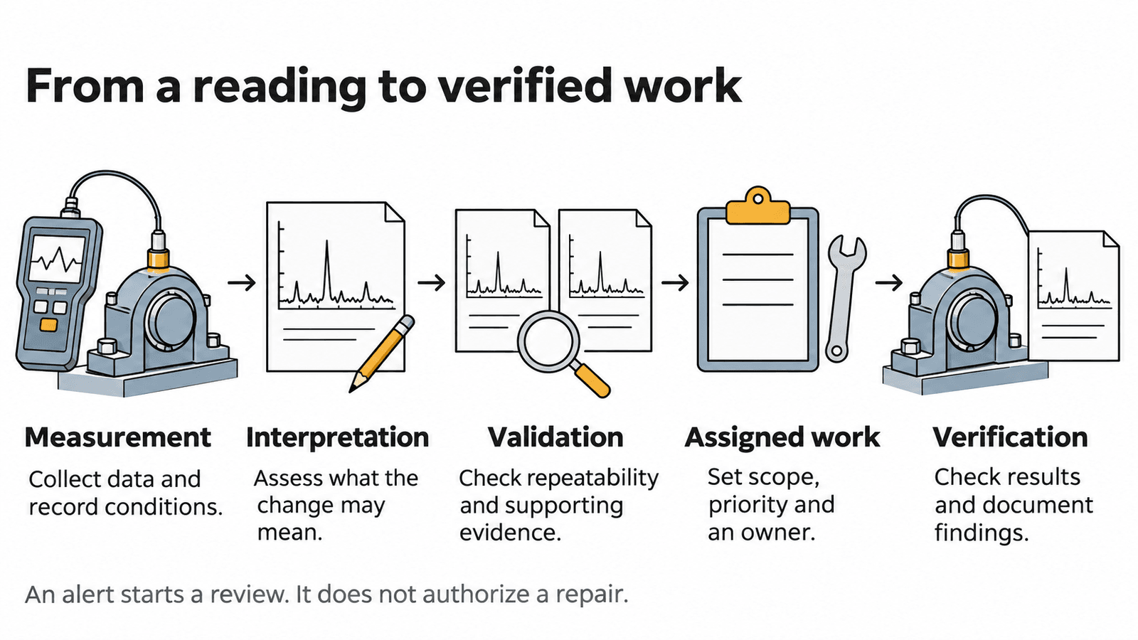
Define who takes the alert and who makes the call on what the response should be. The sequence should be from measurement through to interpretation and validation, assignment of work and then to verification. The evidence and operating context must be captured in the work record. Following intervention you must record what you found and whether the subsequent measurements support closure of the concern. The alert in itself does not authorize repair.
Periodic Inspections or Continuous Monitoring
Fixed or portable is about the instrument itself (i.e. its configuration); periodic or continuous is about the method of collection. Online and offline testing in this context refers to the equipment running or stopped, respectively, not whether or not it has internet access.
When Periodic Inspections Make Sense
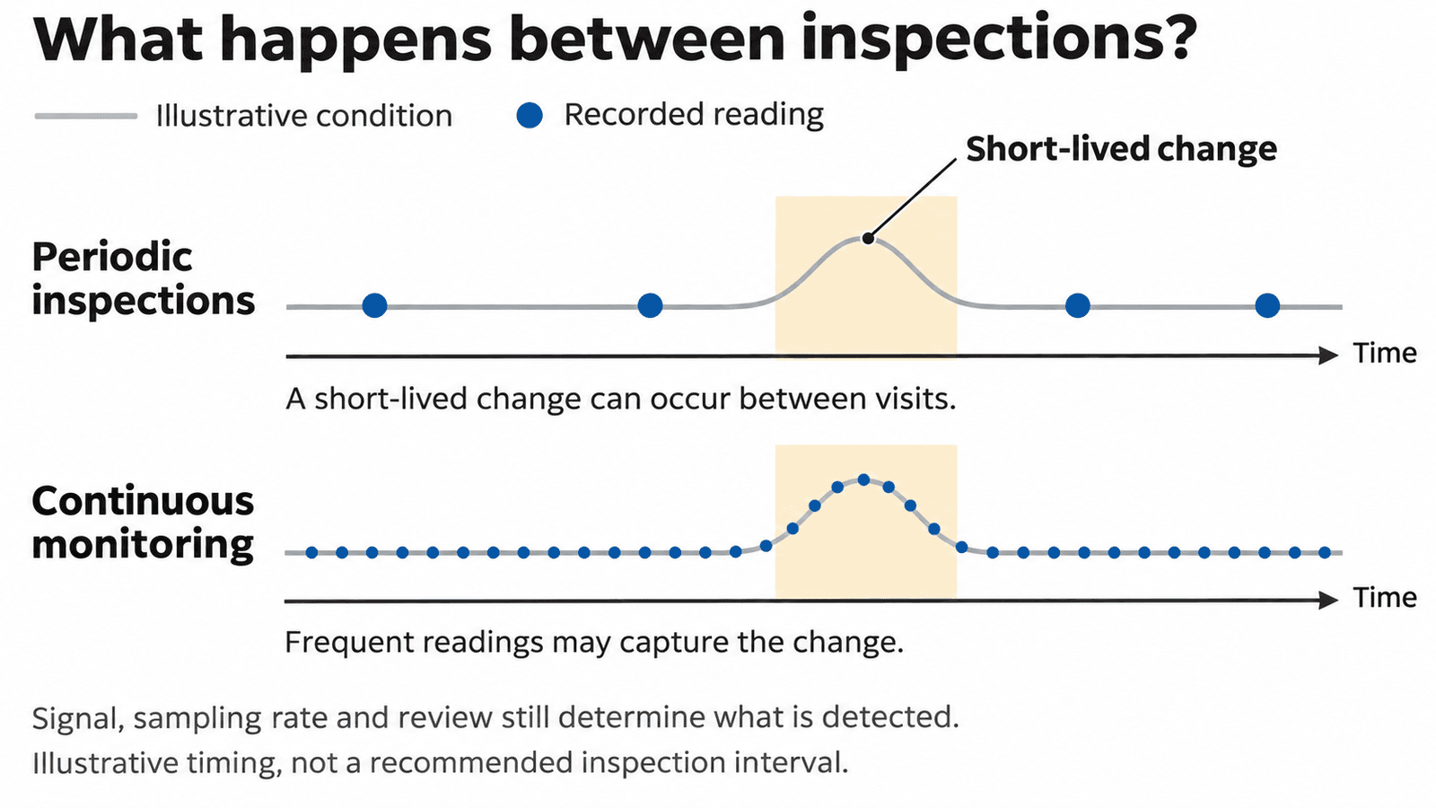
Periodic routes can be appropriate where the asset is accessible and the target deterioration is detectable with sufficient lead time to react. Set the intervals around the failure mechanism, the consequences and the available warning rather than just defaulting to a 'one size fits all' monthly route.
Confirm that the route covers all the required locations and all the required operating states and that different technicians would be able to take comparable measurements. Think about the total delay between observation, analysis and action. A condition that develops and progresses between visits could easily be missed. Consider the inspection intervals in the light of any findings, any access changes and any operating history that would suggest the original plan provides an inadequate response time.
When Continuous Monitoring Is Worth Considering
Continuous monitoring is definitely worth considering in situations where failure has serious consequences, access is difficult and/or where periodic visits may well miss the pertinent changes. You need to make sure the system is actually capturing the required signals at an appropriate sampling rate, that it is holding the diagnostic information and that it is recording the operating context.
Frequent summaries and continuous waveform storage are two very different propositions. You need to ask how transient events are captured, how missing data is flagged and who actually looks at the findings. The most obvious case for intensive monitoring is where there is a specific decision to be made and the owner is in a position to act within the useful time window.
How to Choose Predictive Maintenance Technologies
Start With Assets and Failure Modes
Start with the function the asset is required to perform and the consequences of it failing to perform that function. Then list the failure modes (i.e. the ways in which it can fail to perform that function). An objective such as 'monitor the motor' is far too generic to allow you to pick a measurement or assess coverage. NASA's reliability-centered approach is to link the maintenance decisions directly to the functions and the failure modes.
For each consequential failure mode identify a detectable symptom and write down what the decision would be on that. Would the finding lead to another test, more intensive monitoring, planned corrective work or an operating restriction? How long would it take to confirm the condition, get the resources and carry out the response?
Choose methods which will allow you to observe the relevant symptom while that response is still of use. Some failure modes will provide absolutely no useful detectable warning at all and will require servicing, redesign, protection or some other form of risk control. Be very clear about those coverage gaps.
Check Detection Capability and Operating Conditions
Take the proposed measurement and turn it into requirements. Where is it to be measured? What speed and load range? What access? What environment? What is the required frequency range or test capability? What is the collection interval? What level of detail is the analyst going to need? The requirements should be driven by the failure concern rather than the features that you would put in a sales presentation.
What evidence is there that the method actually detects the condition of interest on similar equipment? What are the limits of that evidence? A successful demonstration under steady load may not validate performance across your operating range. Vendor claims have to be treated as questions that need to be answered by appropriate measurements and competent assessment. NIST's work is very much about the verification and validation of the monitoring capability.
Confirm access to the raw or diagnostic data and work out how a finding can be independently checked. Look at sample reports with the people who are going to be using them and make sure they can identify the observation, the interpretation, the uncertainty, and the recommended action without having to depend on the color coding.
Compare Total Effort and Prove Value in a Pilot
Compare the proposals on the same failure modes and coverage. Include installation, route labor, sampling, lab work, analyst time, training, software, integration, calibration, batteries, and support as appropriate. Factor in the plant's contribution even if an external service is doing the analysis. Low equipment cost can absolutely exist alongside very high recurring effort.
Set the pilot acceptance criteria before collection begins. You need usable data under representative operating conditions, credible findings where assessable conditions exist, a manageable review workload and assigned responses. You need to define how findings will be confirmed and how the completed work will be verified.
Assess false alarms and missed faults where there is independent reference evidence. If there's in fact no relevant fault during the pilot then it can demonstrate the collection and the workflow, but an absence of alarms doesn't prove fault detection performance. Be mindful of that limitation when you're considering whether to go any further.
Example of Selecting Technologies for a Pump and Motor
Match the Failure Modes to the Measurements
Consider the case of a hypothetical fixed-speed centrifugal process-water pump (driven by an induction motor). Both the pump and the motor have grease-lubricated rolling-element bearings and no oil reservoir. Flow and load will vary as normal and an unplanned outage will of course interrupt production. The site inspection history also indicates a reasonable level of corrosion concern in the piping to which the pump is connected.
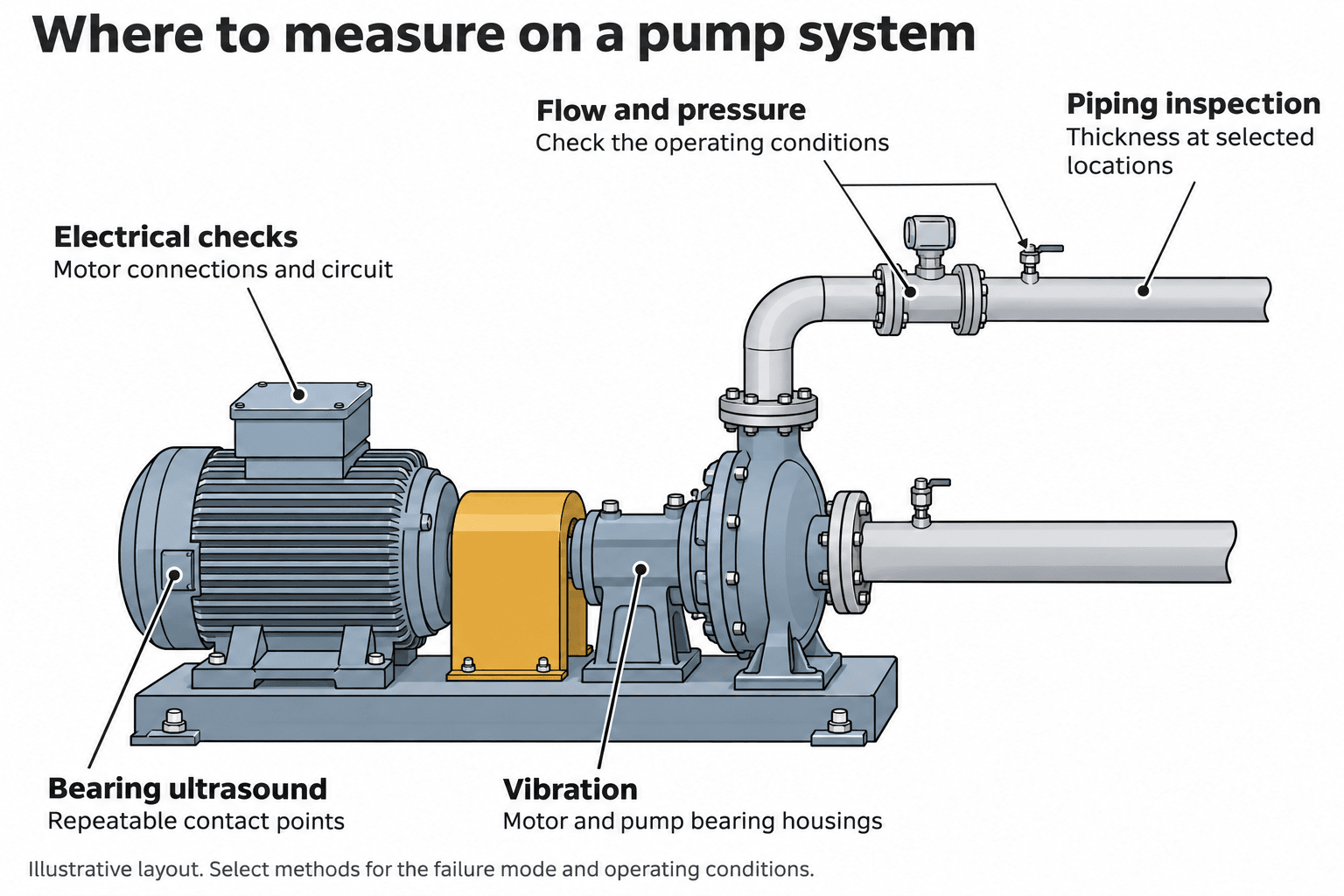
Table B links each concern to the relevant evidence. The performance checks are based on the principle of assessing the performance of the pumping system in its actual operating context.
Failure concern | Chosen measurements | Check before deciding |
|---|---|---|
Bearing or alignment concern | Vibration; targeted ultrasound for bearing condition | Confirm operating state and diagnostic evidence |
Hydraulic performance loss | Flow, pressure, and power | Compare at a suitable operating point |
Electrical connection heating | Qualified thermography and appropriate electrical tests | Confirm load, cause, and safe test conditions |
Piping wall loss | Targeted thickness inspection | Confirm locations, method suitability, and integrity assessment |
Each method answers a different question and it doesn't necessarily have to indicate a defect. Piping inspection is a separate integrity activity driven by the corrosion issue. Routine oil sampling is not applicable as there is no oil reservoir. That doesn't mean grease analysis is out of the question or that every pump will require the full measurement package.
Turn the Findings Into Work and Verify the Result
Suppose the vibration trend changes. Start with collection repeatability, sensor mounting and operating conditions. Compare the appropriate diagnostic detail against the baseline and use targeted corroboration where it can help tell the difference between a mechanical fault and a change in operating condition. The trend by itself tells you neither what the fault is nor what the remaining life is.
Have a competent person assess the evidence and the implications of delaying. If the finding supports work, then assign a sensible scope, priority, and responsible owner. Record the measurements, the interpretation and the residual uncertainty so that both the planner and the technician understand why the task is there.
After intervention document the physical findings and remeasure under comparable conditions. Confirm that the evidence supports the intended outcome before you close the issue. If the trend continues then review the diagnosis and the work that has been done.
Common Technology Selection Mistakes
Buying before you've even named the failure modes leaves you with equipment whose readings may well not be answering the most important questions for the asset.
Gathering data without sufficient diagnostic detail leads to alerts which will then require further investigation before you can justify a repair or even explain the change.
Comparing readings from different operating states can turn normal production variation into what looks like a fault and thus erode confidence in the monitoring process.
The notion that one sensor or one AI model will cover all failure modes is fundamentally flawed and will leave a whole host of failure modes unexamined. Different failure mechanisms will produce different physical symptoms and/or provide little or no useful warning at all.
Producing findings without an owner or follow-up means that legitimate concerns can stay unresolved and the team never gets the chance to find out whether its recommendations were correct.
Identify a critical failure mode, pick an appropriate measurement and prove that the team can take a credible finding and turn it into verified action.
Frequently Asked Questions About Predictive Maintenance Technologies
Which Predictive Maintenance Technology Should a Plant Start With?
Start with a significant asset and a plausible failure mode, then pick a method that will detect a useful symptom. Vibration might be a good choice in the case of a bearing on a rotating machine if you're able to collect and analyze the data appropriately.
Do Predictive Maintenance Technologies Require AI?
No. The measurements, the trends, the appropriate diagnostic analysis and the informed maintenance decisions can all be used to support the work without any requirement for machine learning. The AI system should perform well with the data and operating conditions that are actually available. You need to look at its errors and the amount of review it generates before you can even consider whether it's in any way improving the existing decision process.
Is Continuous Monitoring Necessary?
No. Select the collection interval around failure progression, consequences, access and the time to respond. Periodic inspection can be appropriate where you have sufficient warning. Permanently installed sensors don't necessarily sample continuously so you need to confirm both how often the measurements are taken and what diagnostic information is actually stored for review.
Can These Technologies Predict the Exact Failure Date?
Typically a credible finding would be sufficient to justify an investigation or a maintenance decision rather than give you an exact date. A remaining-life estimate will of course require a suitable validated model, relevant data, stated assumptions and uncertainty. Operating conditions may well change and that will affect the estimate. Treat a forecast as evidence for a decision rather than as a countdown.
Can Predictive Maintenance Technologies Replace Preventive Maintenance?
They can be used to support the replacement of certain scheduled tasks where the failure mode, detectability, applicable requirements and economics all support it. They do not eliminate all time-based or usage-based work, inspections and servicing. Assess the purpose of each task and retain the measures that are required for failure modes which monitoring is not able to detect or manage.
Related Articles
Vibration Analysis: Techniques, Tools, and Benefits
Condition-Based Maintenance vs Predictive Maintenance
How to Evaluate Wireless Condition Monitoring Solutions for Your Needs
How to Start a PdM Program: Predictive Maintenance Steps and Worked Examples
Combining Predictive Maintenance Technologies for Smarter Decisions
Sources
[1] International Organization for Standardization. ISO 17359:2018 Condition monitoring and diagnostics of machines: General guidelines. January 2018. Public catalog scope.
[2] National Aeronautics and Space Administration. Reliability-Centered Maintenance Guide for Facilities and Collateral Equipment. September 2008. Chapter 6; Chapter 3 for the reliability-centered selection framework.
[3] U.S. Department of Energy and Pacific Northwest National Laboratory. Operations & Maintenance Best Practices: A Guide to Achieving Operational Efficiency. Release 3.0, August 2010. Chapter 6.
[4] National Institute of Standards and Technology. Monitoring, Diagnostics and Prognostics for Manufacturing Operations. Updated March 26, 2025.
[5] FLIR. How Does Emissivity Affect Thermal Imaging? November 1, 2021; accessed November 16, 2026.
[6] U.S. Department of Energy and Hydraulic Institute. Improving Pumping System Performance: A Sourcebook for Industry. Second edition, May 2006.
[7] Occupational Safety and Health Administration. 29 CFR 1910.333 Selection and use of work practices. Online regulatory text, accessed November 16, 2026.