By Howard Penrose and Matt Knuth
Vibration analysis is a powerful diagnostic tool for identifying mechanical and electrical issues before failure. When executed effectively, it enables predictive maintenance, reducing downtime and preventing catastrophic breakdowns. However, achieving such outcomes requires careful planning, proper equipment placement, and adherence to established standards.
This article provides a basic guide on best practices for setting up and implementing a successful vibration monitoring program, focusing on the critical aspects of sensor placement, vibration transmission, excluding surface preparation, and compliance with industry standards.
Sensor Placement: The First Step to Reliable Vibration Data
Accurate vibration analysis begins with sensor placement. Otherwise, it does not matter how good or bad the sensors are; if placement is poor, then it can be grossly inaccurate. For instance, in Figures 1-4, the placement of the vibration sensor resulted in good readings. The defects were detected from the MCC with ESA and were audible. The motor was brought to a motor repair shop for evaluation.

Figure 1: Sensor location away from the bearing housing or end shield, also not in alignment with the load, resulting in good readings.

Figure 2: Opposite drive end bearing inner race from the motor in Figure 1.

Figure 3: Drive end outer race with fluting even with the shaft brush.

Figure 4: The stator winding from the rotor scraping during testing as the rotor fell from the ODE bearing damage.
The site in question was experiencing a serious problem of continuous bearing failures even with a continuous monitoring vibration program. A visit to the site identified applications such as Figures 5 and 6 throughout and on hundreds of motors, including critical machines at the pharmaceutical facility.

Figure 5: Wired transducers at the facility.

Figure 6: Wireless transducer placement.
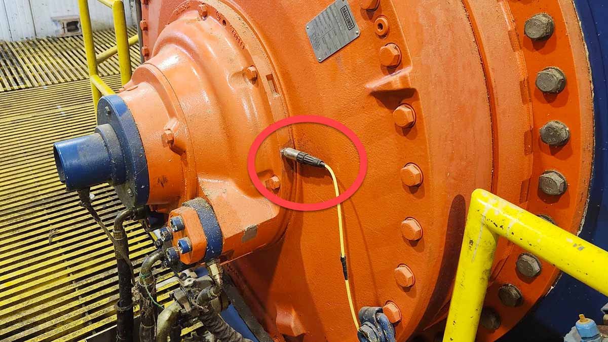
Unfortunately, most vibration continuous monitoring and sensor location placements are similar to the above, such as the sensor placements in Figure 7 at a metals facility.

Figure 7: One horizontally mounted triax relatively close to the DE bearing but on the thin part of the housing, the ODE sensor on a hollow part of the housing well away from the bearing.
How Vibration Transmission Affects Sensor Accuracy
There are physical principles behind the selection of vibration transducer placement. In this case, we will ignore location, shape of landing, fastening methods, paint, and numerous other considerations and just focus on location and position. We will also consider single-axis accelerometers and a simplified single-degree-of-freedom (SDOF) model.
The locations where you can place a transducer include:
- At the shaft and bearing assembly.
- Bearing to end shield.
- End shield to motor frame.
- Motor frame to external mount or fin.
While we have not shown images of location 1, the other three are well represented in Figures 1-7.
Each path can be approximated to a damped spring-mass system. The measured vibration at a given point depends on how that path transmits or attenuates vibratory energy. For instance, the bearing region, such as the bearing housing, typically experiences the greatest transmission ability for bearing-related frequencies.
As we move further away (e.g., to the top of the end shield or out on the motor frame), structural dynamics can filter these vibrations, either damping or amplifying them, and filter out high frequencies used for early bearing detection.
Different points on a motor will have different local resonances. A thin-walled end shield, for example, may exhibit a bell mode that resonates at certain frequencies, leading to amplified readings even though it may be physically farther from the bearing.
The equation below contains a standard SDOF model with mass m, damping c, and stiffness k, subject to a forcing function F(t).

If the force is harmonic, F(t)=F0ejwt, the steady-state displacement amplitude at frequency w can be written in complex form as this equation:

The analysis becomes more complex as we consider displacement at the rotor or bearing. The transmissibility T(w) is then the ratio of the output displacement amplitude Xout(w) at the measurement point to the input displacement amplitude Xin(w), as shown below.


Real electric motors have multiple resonances including end shield ringing (bell) modes, stator laminations, unbalance, etc., with the total transmissibility at each frequency generating a highly complex system.
Longer structural paths through more joints and interfaces add damping or stiffness changes, filtering out critical high-frequency signals used for early fault detection.
When considering the location of the bearing transducers, you must consider that longer structural paths through more joints and interfaces add damping or stiffness changes. As you move further from the bearing, the vibration behavior is influenced by multiple structure resonances and boundary conditions.
To make matters more interesting, when you move to any indirect path to the bearing, overall amplitudes may be lower due to damping; however, certain frequencies may align with frame resonances, generating unexpected peaks. This means:
- Near the bearing: direct path resulting in minimal structural filtering due to less mass and stiffness in series. Bearing impulse forces or spalls on the bearing races couple directly to the sensor.
- Top of the end shield: an intermediate path vibration must travel through the bearing seat and end shield structure. Thin sections of the end shield may cause ringing effects that can amplify certain frequencies and hide others.
- Further away from the end shield on the frame or housing: A longer structural path with more joints and interfaces adding damping and/or stiffness. Overall amplitudes may be lower due to damping; however, certain frequencies may again align with frame resonances, causing unexpected peaks.
Placing the transducer(s) far away from the bearings ensures you won’t see high frequencies associated with early bearing defects, allowing for confirmed detection audibly before vibration.
Following ISO 20816-3 Standards for Accurate Sensor Placement
When considering the placement of transducers, care must be taken. Luckily, there is an ISO Standard 20816-3: 2022, “Mechanical Vibration – Measurement and Evaluation of Machine Vibration – Part 3: Industrial Machinery with a Power Rating above 15 kW and Operating Speeds between 120 r/min and 30,000 r/min. In the standard it states in Section 4.2, ‘Measurement Location:’
“Measurements taken on non-rotating parts shall be taken on the bearings, bearing support housing or other structural parts which significantly respond to the dynamic forces transmitted from the rotating elements at the bearing locations and characterize the overall vibration of the machine.”
There is a discussion of placement should there be challenges for direct bearing housing measurement in order to obtain the best possible readings, but also identifying the different limitations.
ISO 20816-3 emphasizes sensor placement on structural parts that directly respond to forces from rotating elements at the bearing locations.
The standard then identifies that there would be two radial measurements per bearing, often a vertical or horizontal, or at least one that provides a maximum vibration reading. There is normally also an axial reading as close to the shaft as possible in order to maintain accuracy.
This is not something new, even back in 1993, in an IRD Mechanalysis seminar Level 1, in Chapter 8, the rules for data collection included:
- Choose proper measurement locations: The location should be as close to the bearings as possible. Try to locate the points within the bearing’s load zone. If it is a sleeve bearing, this is especially important, but it is outside the scope of this article.
- Do not compromise safety for the location.
- Take horizontal measurements as near to the horizontal shaft centerline as possible.
- Take vertical measurements as near to the vertical shaft centerline as possible.
- Take axial measurements parallel to the shaft being supported by the bearing and make the measurement at the same location each time.
- Do not assign measurement locations to thin/weak sheet metal, such as on some motor end bells or fan covers. Modifying a fan cover to obtain good measurements is a recommended practice.
Unfortunately, a review of some of the ‘alternative’ training materials that we’ve observed for beginning vibration analysts, including some from inexperienced instrument manufacturers, tends to bypass transducer placement. Given the gross misapplication of bearing transducers that we have observed, this may be an area that training and certification companies may want to focus on.
Best Practices for Accurate Vibration Transducer Placement
Best practices require that you place transducers as close to the bearings as possible and in the load zone, especially in the case of babbitt-style bearings. In Figure 8, the machine has relatively small bearing housings on the exterior.
The result is that vibration points are placed on the end shields of the motor but in a position that follows a solid path perpendicular to the bearing housing and centerline of the shaft.

Figure 8: Example of proper end shield placement if you cannot mount directly on the bearing housings.
Figures 9 and 10 represent transducer placement over bearing housings, which will allow high-frequency impact and early detection readings to be successful.

Figure 9: Transducers positioned perpendicularly to the bearing. Alternatively, the bottom part of the split pedestal would have been acceptable.

Figure 10: Also at an angle but perpendicular to the bearing offset from a potential cavity.
When developing a periodic or continuous monitoring vibration program, you have a choice. If you wish the program to succeed, proper placement of the vibration transducers is critical. Otherwise, any detection that does occur may be well into severe failure modes, reducing the purpose of a predictive or continuous program: early detection of defects for scheduling and reduced downtime.
When placement is random on the electric machine or on the fins of the motor, then the program will have no better chance of success than a reactive maintenance program.
The reality of critical component detection using vibration can mean the difference between a successful CBM and reliability program or can result in the collapse of the opportunity.


