Partial discharge is an electrical effect that, once upon a time, was only a concern for high-voltage system engineers and technicians.
In systems over 6,000 Volts, rapid electrical discharges, like tiny lightning storms, can occur across surfaces, between surfaces, within insulation systems, and even between cables or cables to ground. When these discharges occur across surfaces or on high-voltage transmission lines, they are often called corona.
Understanding Partial Discharge Across Different Voltage Levels
In the 1990s, with the advent of pulse width modulated variable frequency drives, the conditions that allowed partial discharge to occur dropped to voltages around 200-300 Vac. This is related to how fast each pulse increases to the peak voltage (dV/dt), the impedance of the conductors and motor, the temperature of the insulation system, and any power harmonics on the output of the drive.
The partial discharge occurs in small spaces and between conductors, usually spaced less than one millimeter apart without insulating varnish between them or high potential cross-overs.
In all cases, the result is chemical etching, as the ozone is given off due to the discharges in the air. The ozone degrades insulating materials and other dielectrics, such as paint, leaving an etched appearance that is often misidentified as a powdery substance.
Partial discharge isn’t just a high-voltage issue anymore—it’s a growing concern even in low-voltage systems with VFDs.
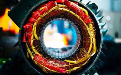
In low voltage, random wound motors, the weakness tends to occur where stray conductors exist in the end turns or where a conductor crosses several other conductors in the same or a different coil.
The stress that causes extreme forms of this type of partial discharge generally occurs when the drives are not set correctly and/or specific distances are met between the motor and drive.
In some cases, it is essential to keep connection box conductors from being pressed against the inside of the connection box, resulting in a grounded condition caused by both partial discharge and vibration.

Figure 1: Electric motor winding in which conductors are loose and crossovers coil that make it susceptible to partial discharge failure.
Ozone attacks the electrical insulation system, gradually removing material and changing it chemically. This breakdown will eventually allow for a short to ground or between conductors, depending on where the defect occurs.
In medium voltage (>1000 volts) and higher cables, if it carries high harmonic content or is associated with a VFD if leaning against the inside of a cabinet or transformer enclosure, you may notice discoloration on the housing or cable where it is in contact. This can also occur in splices when they are not set up correctly or become contaminated.

Figure 2: Cable discharge on a 4160 Volt cable feeding a VFD
The Chemical Impact on Insulation Systems
In motor systems over 6kV, partial discharge (internal) and the corona (surface) occur due to power, temperature, load, and harmonic content.
Small voids in the coils between conductors or in the tapes and varnishes that make up the coil outer insulation, and then between the coils and stator frame, become points for partial discharge. Dirt, contamination, and even humidity generate corona effects on the surfaces of the insulation system.

Figure 3: Visual Acoustic testing for partial discharge and corona.
The types of methods and patterns associated with partial discharge and corona are identified in IEEE and IEC standards that include IEEE 1434 for machines, IEEE 2862 for cables, IEC 60270 for cables and switchgear, as well as several others in both IEEE and IEC standards.
Most detection systems include amplitude-modulated antennae to detectors (RTDs and capacitors), corona cameras, ultrasound instruments, visual and acoustic cameras, and electrical signature analysis.
Detecting and Mitigating Partial Discharge: Tools and Techniques

Figure 4: Slot partial discharge of a 13.8 kV generator. The red arrow indicates conductive tape (black), and the blue arrow indicates missing conductive tape from slot partial discharge. The white tape is the remaining armor tape.
Partial discharge and corona are long-term failure processes usually determined in years. Changes in partial discharge signatures and values are trend-able for assessing the risk of failure with limits depending on the types of insulation systems involved.
When detected, some mitigation is possible, usually involving power correction and/or cleaning components. However, most instances require more aggressive repair, such as insulation replacement.


