When we are called out on service calls to test long-term failures in variable-frequency-driven environments, we sometimes encounter unique situations that bypass applied best practices, such as high-frequency harmonics caused by other conditions.
However, the more common finding is that someone in the organization, such as a purchasing agent, engineer, or vendor, makes an uninformed decision to bypass best practices. In the following case study, years of problems with an application resulting in bad belts, failed motors, failed drives, and other conditions that the plant was unaware of, resulted from a comedy of application conditions.
Initial Observations and Testing Approach
An analysis was performed on a machine used in a food processing environment. There was a high rate of motor and VFD failures on critical production equipment, prompting a recommendation for MotorDoc personnel to perform testing and evaluation.
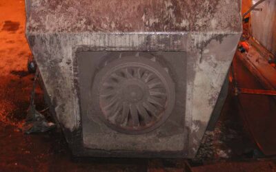
Once arriving and observing the application (Figure 1), we selected a combination of an EMPOWER MCSA and an EMPATH ESA system. It was determined that production would not be shut down to access voltage test points, so we decided it was safer to focus on current-only measurements, which are more than sufficient for this type of application.

Figure 1: Testing locations including the line reactor
Evidence of Improper VFD Setup and Configuration
The system is 480 Volts connected to a 300 hp, 1785 RPM electric motor with sheaves and belts. While we were unable to see the motor directly, the repair report does not show shaft brushes or an opposite drive end insulated bearing.
The VFD has a line reactor between the disconnect and the VFD, so data was obtained between the disconnect and line reactor for incoming power and the output of the drive for motor testing. The VFD has a firing frequency of ~2 kHz, which has surrounding VFD firing peaks of -20 dB as measured on the output of the VFD to the motor.

Figure 2: High frequency dB levels that reference the RHI at -20dB at 2 kHz

Figure 3: RHI chart reference (reference Supra Harmonics in VFD Systems: A New Frontier in Reliability Risk)
Root Causes: Harmonics, Filters, and Ground Currents
On the output side of the VFD to the motor (Figure 1), the RHI values of -20 dB at ~20 kHz relate to potential impacts on windings and bearings. Ground currents have a -0dB value at 2 kHz on the ground cables back to the drive from the motor, which is indicated by the EMPOWER and related currents of 2.5 Amps peak.
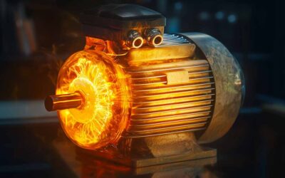
This identifies conditions that must be addressed immediately. As shown in Figure 4, the ‘noisy’ currents result in these conditions, which also result in the bearing damage and winding stress shown in Figure 5.

Figure 4: Current waveform from VFD to motor.

Figure 5: Electrical and mechanical components.
Corrective Actions to Restore System Reliability
The resulting potential shaft currents, common mode ground currents, and other conditions related to bearings and winding conditions are generated by the outputs of the VFD. The drive settings require that the drive be tuned following motor replacement and initial installation.

Figure 6: The incoming current before the line reactors on both VFD systems appears the same way with very high THDc and a high TDD (ref. IEEE 519).
The current measured before the line reactor shows that the line reactor is very much ineffective with very little change on either side appearing as in Figure 6. This indicates that the line reactor is not sized correctly, and either a different line reactor or an isolation transformer is required.
A second identical VFD system was evaluated with the same results, indicating that the problem is most likely the line reactor sizing. No information or drawings were available to provide the sizing used.
Also found on the second VFD incoming power before the line reactor was RMS current that appears as in Figure 7. This oscillating current, which appears similar to a rotor bar condition, identifies conditions related to damaged capacitors in the DC bus (VFD).

Figure 7: Oscillating current before the line reactor, indicating possible damaged drive.
In conclusion, several conditions must be addressed in these applications to reduce or eliminate damage to the motor bearings, windings, and variable frequency drives. In addition, other conditions may be occurring elsewhere in the electrical system due to the current harmonic content. These can be eliminated in this application through the following:
- Properly sizing filters at incoming power to the VFD and to the motor, as required. See How Misapplying IEEE 519 Affects Inverters and Harmonic Distortion for more information.
- Ensuring that drive settings are correct, and when set other than volts per hertz, ensuring that the drive is auto-tuned before the first application and after any motor repair or replacement.
- Even when output filters and correct cables are used between the VFD and motor, the application of an insulated ODE bearing and shaft brush is usually best practice.
There was the consideration of a repair center that the belted application required roller bearings. The measurements by the EMPATH and EMPOWER systems did not indicate an excessive overhung load or overtension that would necessitate the use of roller bearings. However, the measurements in torque suggested that there is sufficient load on the roller bearings for their intended use.
The machines were normally run well beyond the failure of the bearings, which would allow investigation of potential fluting. However, measurements indicate that bearing fluting and winding stresses, which lead to winding failure, are occurring in this application. Application of the three best practices above would resolve these issues, including the VFD failures.

Howard W. Penrose, Ph.D., CMRP, CEM, CMVP, is president of MotorDoc® LLC, a Veteran-Owned Small Business. He chairs standards at American Clean Power (2022-25), previously led SMRP (2018), and has been active with IEEE since 1993. He represents the USA for CIGRE machine standards (2024-28) and serves on NEMA rail electrification standards (2024+). A former Senior Research Engineer at the University of Chicago, he’s a 5-time UAW-GM Quality Award winner. His work spans GM and John Deere hybrids, Navy machine repair, and high-temperature motors. He holds certifications in reliability, energy, M&V, and data science from Kennedy-Western, Stanford, Michigan, AWS, and IBM.