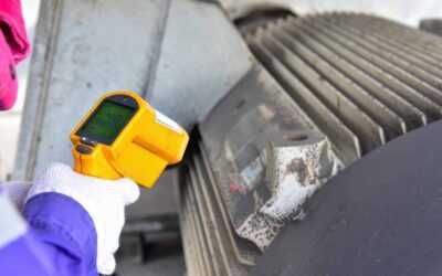

Over the past four years, we have seen an increase in field troubleshooting calls related to catastrophic failures of specific types of equipment. When failed components are reviewed, from melted bearings to damaged rotors and windings, and reported back as ‘the motor was overloaded,’ there is pushback, even from the equipment package companies, that the settings are correct.
Field testing of several packaged systems over time has revealed that motors with service factors ranging from 1.0 to 1.2 are regularly loaded to between 150% and almost 200% of their rated capacity.
Just because a motor doesn’t stall doesn’t mean it isn’t overloaded.
One comment was that the control settings were fine and the motor would have immediately burned up or stalled if it were overloaded, which is false. However, the responses appear to be geared towards non-technical company personnel or those who do not understand motor applications.
Common Misunderstandings About Motor Overload Behavior
The electric motor nameplate is a legal document. The limits and capabilities etched onto this document adhere to specific standards, and deviations from the standards are also specified on the nameplate.
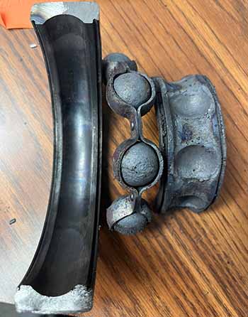
Figure 1: Bearing from an overloaded air compressor, including inner race melting from loss of clearance.
For instance, if the motor is capable of 1.5 times its nameplate rating, then the service factor would be at least 1.5. If it were on an inverter, that service factor would be identified as possible on a Variable Frequency Drive (VFD). This value is based on the machine’s insulation system design.
The torque output of a motor, especially a standard motor, follows a torque curve. Most of the motors we’ve observed have been Design B, or equivalent, which has a breakdown torque limit of 200%, or a point at which the motor experiences a drastic change in speed or stalls.
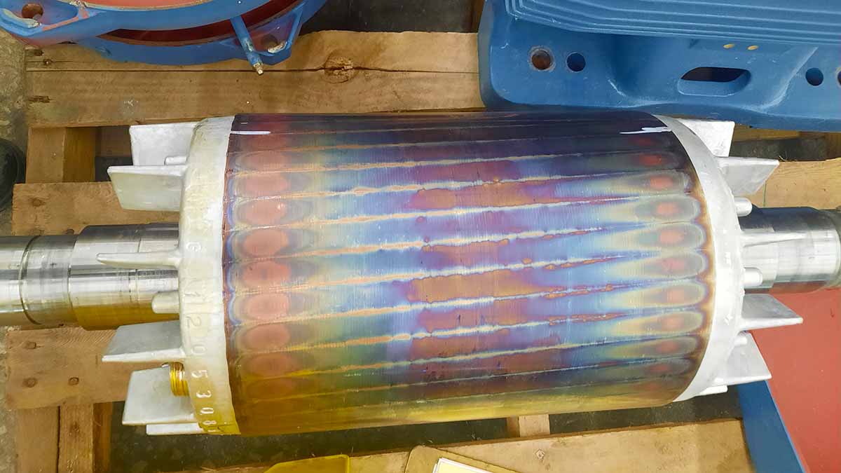
So, while loading close to 200% will not stall the motor, especially if the voltage is too high, the current and heat at the motor will be excessive, and the rotor will be extremely hot. It may discolor, and the shaft will expand, reducing or eliminating the clearances in bearings. Forcing extra air across the motor does not cure this issue, as other electrical and magnetic field properties also become problematic.

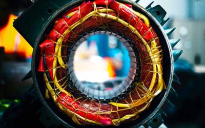
Figure 2: Rotor loading and harmonic content heating impact.
Why Insulation Ratings and Nameplate Data Still Matter
Standards such as IEEE 117 and IEEE 1776, IEC 60034-18-31, and IEC 61857 are relevant to thermal testing for selecting the insulation rating. UL 1446 is the UL standard that outlines the testing protocol for determining the thermal life curve and rating of these machines.
Some value, such as 20,000 or 25,000 hours, is used to identify the expected life at the rated value, such as Class F or 155°C. As many motor manufacturers offering extended warranties typically use insulation systems at least one class higher than what is required to protect against improper application, that step is not intended to allow motor overloading.
Overloading also blows away any attempts at improving motor efficiency and power factor correction. However, if you load the machine to a point where it reaches 155°C, whereas the motor, properly loaded, might reach 120°C, you end up with a machine that effectively has a 2-3 year insulation thermal life, assuming everything is perfect.
Overload quietly shortens the insulation life, even when the motor is running.
When checking the setup and loading of your machine, ensure that you operate within the motor’s nameplate capabilities. This includes the service factor, protective device sizing, and thermal class of the motor.
If the motor does not identify anything differently on the nameplate, then the service factor relates to the motor operating at line frequency and voltage. Just because a motor does not stall at 150% to just under 200% load does not mean it isn’t overloaded.
More information on the proper application of electric motors, as jointly developed by manufacturers, owners, repairers, government, and other stakeholders, can be found at the US Department of Energy Motor Challenge.