
When reviewing the IEEE and EPRI large electric motor studies and what was considered ‘excellent maintenance,’ it is quickly noted that a lot of the technologies we use now for trending and prognostics were not included or considered.
Before the 1990s, high-voltage testing, including high-potential and surge comparison testing, was primarily performed by utilities and repair shops to evaluate existing and repaired electric machines. To this day, surge comparison and many of the other tests conducted as part of modern prognostics and trending to detect defects are not required to be performed by manufacturers with a focus on insulation to ground.
Once reliability programs insisted on field testing of electric machines for winding shorts and contamination, the need for winding tests increased first with low-voltage testing methods and then later with surge comparison and insulation to ground testing. Additionally, there is a lot of misunderstanding about standards and the different tests used for them.
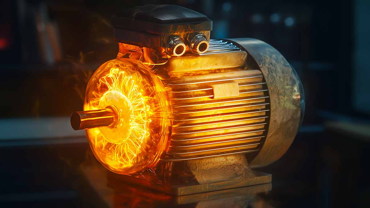
Modern diagnostics demand more than resistance checks—they require voltage stress to expose hidden weaknesses.
Understanding the Role and Risks of High-Voltage Testing
In this article, we will bypass the discussion of insulation to ground testing and resistance testing with the intent of addressing them in a later article. Instead, we will delve into the realm of high-voltage testing and the process you would follow before applying the potentially destructive tests of high-potential and surge comparison testing. For this article, we will be using an Electrom ITIG II Model D 12kV instrument with offline PD and low voltage testing, which is similar to a variety of testers on the market.
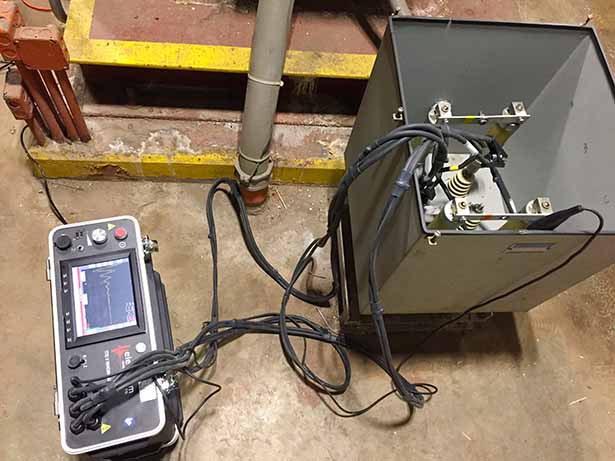
Figure 1: Surge comparison test from a 4000-Vac motor capacitor bank.
The cautions, up front, relate to the term ‘potentially destructive.’ While we’ve heard most manufacturers say that they are not, there are a few things that need to be made clear before experiencing the feedback, “we found your problem,” when a previously functioning motor no longer operates.
The purpose of high-voltage testing is to act similarly to overpressurizing a compressed air system: you will not only find existing leaks, but you will also potentially expose a few weaknesses.
If you don’t plan for failure during testing, you’ve already failed to test safely.
The objective is to identify problems during testing rather than during operation, and a plan must be in place when testing is conducted.
What happens if the equipment fails the test? Can we use the machine for a while longer? Do we have the necessary resources to resolve the issue before proceeding? Are these problems real? If you are performing these tests in the field, you will most likely have had the experience.

Figure 2: High voltage testing at 4000 hp motor connection box.
Understanding high voltage testing is important to reduce the number of potential problems that you will encounter. For instance, when testing large synchronous motors, it is crucial to disconnect the exciter from the circuit or raise the brushes on slip rings to prevent damage to the rotor insulation systems or the electronic excitation package.
We’ve encountered issues where voltage has jumped as much as half an inch, causing damage to diodes in an exciter and breaking down the insulation in a rotor shaft. While most instruments have built-in protection systems, arcing occurring on the secondary (rotor winding) is not easily detected through the stator winding.
Contamination Risks and the Case for Insulation Resistance Testing
Another area of concern relates to contamination. A winding covered in materials such as contaminated grease, oil, and conductive dust can create conditions where an arc can occur between conductors or between conductors and ground. Carbon forms where the arc occurs, resulting in a semi-conductive, temperature-dependent path referred to as tracking. This will either cause the machine to trip immediately or, once the area where tracking has occurred gets warm enough to become fully conductive, it will.
Contamination doesn’t just degrade insulation—it creates the perfect path for electrical tracking.
As a result, steps must be taken to prevent this type of condition, such as insulation resistance testing. The tables and methods from IEEE Standard 43-2013 related to the applied voltage, temperature adjustment, dielectric absorption, polarization index, and minimum insulation resistance values are not really there for testing machine condition.
They exist to determine if you can advance to higher voltage testing with less risk of damaging the insulation system. For instance, after temperature correction, a form-wound stator measures 101 megohms; therefore, it is less risky to apply a high-potential or surge comparison test.
A standard currently in development, the IEEE Standard P97 (P means it is being developed), will provide more details on interpreting insulation to ground, including the addition of the Insulation Resistance Profile (IRP) for identifying specific conditions.
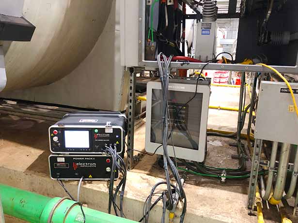
Figure 3: Surge comparison test of 13.8 kV synchronous motor at the connection box with booster pack.
The surge test uses the concept of a ‘tank circuit,’ where a capacitor discharges an impulse that travels to an inductor and a resulting RLC dampening occurs at the peak of the impulses. What this means is that as the fast rise time square-wave impulse travels through the test lead and hits the coils of an electric motor, which are inductors, a ‘ringing’ occurs at the top of the square wave.
If like coils or inductive circuits, such as a winding, has the same inductance then the dampening is the same. Conditions where there are shorts or weakness between conductors show as a difference between ‘like’ inductive circuits. These can also be separated by air; therefore, a voltage significant enough to ionize the air between exposed conductors, as per Paschen’s Law, must be applied.
A perfect surge test reveals imbalance by making invisible inductive flaws ring loud and clear.
One of the challenges with the surge test is that it doesn’t measure defects in parallel conductors. An open conductor, or conductors, amongst a group of parallel conductors will often not be detected by the surge test. This means that you must have a way to identify partially open circuits, such as resistance measurements.
For a large three-phase machine, you can compare the resistance between phases and determine if there are defects. The unbalance depends on which standard that you are following, which may be as tight as 1% unbalance from the average resistance to as high as 5% unbalance in resistance. Resistance is also typically adjusted to 25 °C.
The result of the various concerns surrounding high-voltage testing in the field is that a specific process is typically followed, which builds upon previous testing. These can also include additional tests, which we’ll identify as ‘options.’
There is currently no IEEE or IEC standard that covers the use of surge comparison testing in the field, with the exception of NFPA-70B (2016). However, testing procedures and descriptions were dropped in the 2023 edition, which also changed it from a recommended practice to a standard. The following practices are generally accepted, as recommended in other standards, leading up to the high-potential test.
Key Procedures Before Applying Surge and Hipot Tests
- Resistance check: to verify continuity and circuit balance. Usually corrected for temperature, which can be trended.
- Low Voltage Tests (Option): These would include inductance, impedance, capacitance, and related low-voltage tests to determine if any obvious faults exist. Some faults detected can be corrected, or the higher voltages can be stopped while options are reviewed.
- Insulation Resistance: tested to a specific voltage and insulation resistance value depending on the voltage of the machine. This is used to determine if the insulation system is in poor shape or heavily contaminated. Usually performed in conjunction with the dielectric absorption or polarization index. For random wound machines, after temperature correction, the minimum value is 5 Megohms, and for form wound machines, the minimum value is 100 Megohms.
- High-Potential Test: For this type of instrument, it is usually a DC high-potential test. There are various methods for performing a DC high-potential test, with the least potential harm resulting from a ‘step test,’ where the voltage is increased and then held constant for one minute at each level. The instrument and operator can monitor for a sharp increase in leakage current to ground, typically measured in pico- or micro-Amps.
- Surge Comparison Test, which was usually performed on stators with the rotors removed. Newer methods have been employed that provide peak-to-peak and line-to-line tests, which support fully assembled motor tests. An additional test includes the PD Surge test, which is a measurement of partial discharge that occurs along with the fast rise-time impulses from the instrument. This increasingly popular test can be used on motors that will be applied to inverters to identify where partial discharge may occur and where it may be extinguished, in addition to facilitating earlier detection of insulation breakdown.
Modern Tools, Limitations, and Field Testing Best Practices
For many surge comparison testers, the ‘portable’ units have a limit of about 12kV. Although some higher-voltage testers are appearing on the market, these typically require a booster pack for higher voltages. They will usually be plugged into a power supply, such as a wall outlet, to produce the necessary power for testing. The quality of the power supply, notably if it lacks built-in filters, can produce errors. Many modern surge testers will alert if a bad ground is detected.
Auto-stop features don’t just prevent faults—they prevent costly, irreversible damage.
One of the most significant advancements in high-voltage testing technology is the auto-stop feature. With older analog surge and high potential instruments, the operator could deliberately or accidentally force a fault. In the case of modern instruments, this would require changing specific settings or performing the test manually. There are times when an operator would want to force the fault, such as with root-cause analysis or fault finding.

Howard W. Penrose, Ph.D., CMRP, CEM, CMVP, is president of MotorDoc® LLC, a Veteran-Owned Small Business. He chairs standards at American Clean Power (2022-25), previously led SMRP (2018), and has been active with IEEE since 1993. He represents the USA for CIGRE machine standards (2024-28) and serves on NEMA rail electrification standards (2024+). A former Senior Research Engineer at the University of Chicago, he’s a 5-time UAW-GM Quality Award winner. His work spans GM and John Deere hybrids, Navy machine repair, and high-temperature motors. He holds certifications in reliability, energy, M&V, and data science from Kennedy-Western, Stanford, Michigan, AWS, and IBM.