
The combustion fan motors at the steel plant are 800 horsepower, 1785 RPM, 4160 Vac, 101 Amp AC induction motors designed for severe duty applications and an 80oC ambient temperature. They are manufactured with an external fan which drives air through a series of cooling tubes in the top hood of the motor.
This design is meant to reduce or remove the possibility of external contamination into the electric motor windings. One of the combustion fan motors failed, winding to ground.
The failed fan motor was lowered to the mill floor for additional testing, and the remaining three fan motors and the new spare motor were tested with an EMPATH™ Electrical Signature Analyzer (ESA).

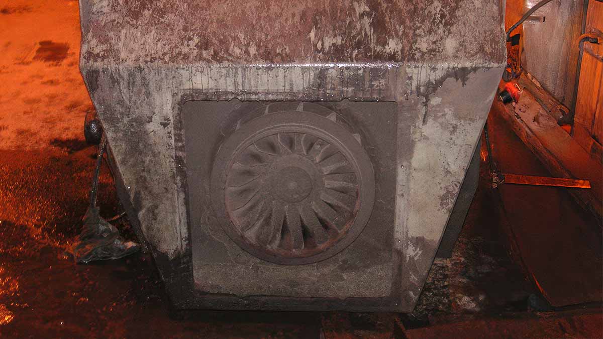
Figure 1: Combustion fan motor on floor.
The motor was transported to a local electric motor repair facility and disassembled for additional analysis to determine the cause(s) of failure.
The purpose for the analysis of the combustion fan motor was to determine optimal recommendations for maintaining and condition-based testing of all of the motors in this system.
The initial inspection was performed on the floor of the mill. The lead connections had been severed. An ALL-TEST Pro 5 Motor Circuit Analyzer was used to evaluate the existing condition. The winding was found to be severely damaged with a direct short to ground. A visual inspection was performed.
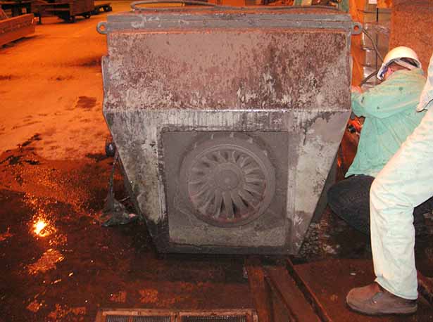
Figure 2: Lead inspection before sending it to the repair shop.
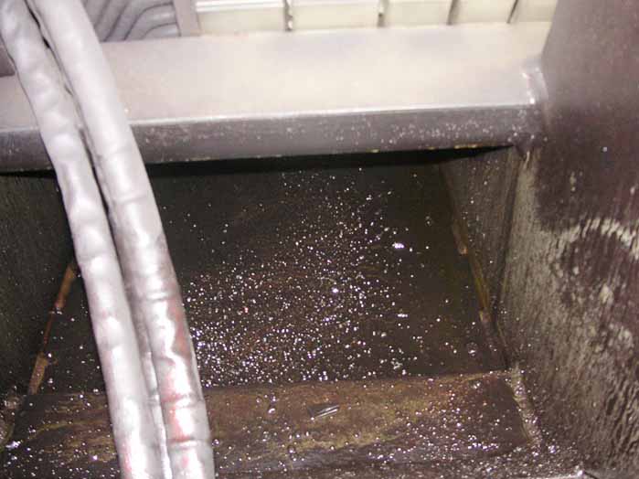
Figure 3: Inside the bottom of the motor housing.
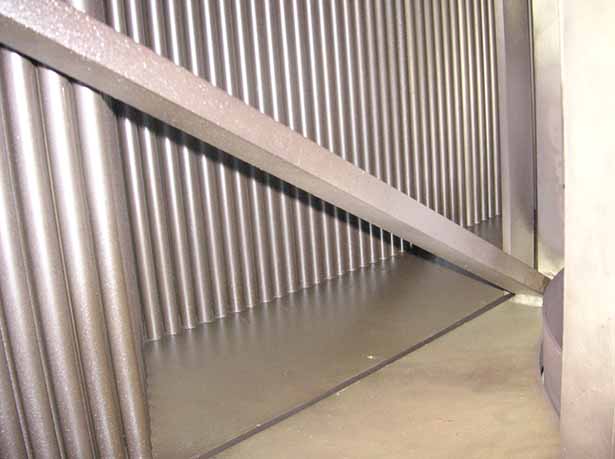
Figure 4: Interior Cooling System of Motor (Picture up from Connection Box)
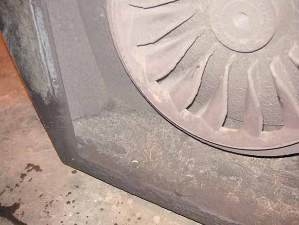
Figure 5: Fan Condition and Contamination
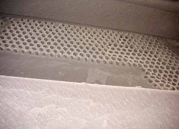
Figure 6: Cooling Tube Openings, Fan End
Figure 3 identifies copper balls on the bottom of the motor related to a catastrophic winding failure. The inside wall of the motor on the right side of the picture identifies the ‘water line’ of oil that was trapped in the motor.
Figure 4 identifies the cooling tubes which provide heat exchange with the air within the motor. Fans on the motor rotor cause the air to move within the stator and through the cooling coils. Air moving from the fan through the inside of the cooling coils carries the heat out from the electric motor. The cooling coils inside the hood of the motor are relatively clean.
Figures 5 and 6 identify the contamination prevalent through the air-cooling system, clogging the ability of the motor to cool itself.
ESA Evaluation of Combustion Fans
ESA was performed on the three remaining combustion fan motors and on the spare combustion fan that replaced the failed motor. As shown in Figure 7, the only data that could be safely taken was current signature data. In each case, fan frequencies were identified showing some level of fan unbalance and loose coil signatures.

Figure 7: ESA Data Collection Points

Figure 8: Typical Low Frequency Signature
Figure 8 represents the low frequency (<100Hz) signature from a different combustion fan. RB1 and RB2 identify Pole Pass Frequency (PPF) signatures around line frequency. These peaks identify fractures in at least one rotor bar and this situation should be monitored with the fan under load.
F1 and F2 identify fan unbalance signatures which identify that the fans on the motor and the combustion fan should be cleaned. RS represents the running speed, and the height of the peak identifies that the direct drive fan and motor are mechanically imbalanced. Based upon the general cleanliness of the failed Combustion Fan #4, cleaning of the fans, cooling tubes and combustion fan may be what is required to correct any unbalance.

Figure 9: High Frequency, Stator Mechanical (SM)
The peaks entitled SM1 and SM2 indicate ‘Stator Mechanical’ issues that are prevalent in all of the combustion fan electric motors. These peaks normally indicate movement of the stator coils.
Disassembled Motor Investigation
The failed combustion fan motor was disassembled at a local motor repair facility.
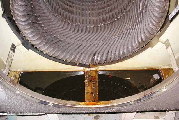
Figure 10: Oil filling the bottom of the motor.
As shown in Figure 10, oil was introduced into the motor through the bearings. The oil level in the motor had reached the level of the windings, as shown as a ‘water line’ in the motor. At the time of motor disassembly, approximately 1-2 inches of oil remained in the motor. Figure 10 identifies the winding at the drive end of the motor where oil had been leaking directly onto the windings.
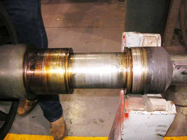
Figure 11: Failed Seal Surface on the Rotor
The rotor side seal surface of the rotor for the bearing failed, as shown in Figure 11. This appears to result from poor original (OEM) seal dimensions, which allowed oil to enter the motor.
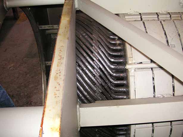
Figure 12: Motor Coils
Figure 12 identifies the coil end-turns and the blocking involved. Just out of sight, under the metal stator strut, is the surge ring, which is a band around the outside of the coils to provide additional mechanical strength.
The blocking and position of the surge ring are insufficient to properly hold these coils, mechanically, allowing movement, which explains the ESA mechanical coil signatures. This movement can cause stress fractures in the insulation system at various points of the end-turns of the coils, in particular where they exit the stator slots.
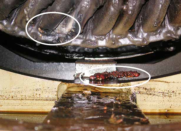
Figure 13: Failed Coil Material
The material below the winding in Figure 13 is copper that had been melted at one of the winding failure points seen in the upper left at the surge ring.
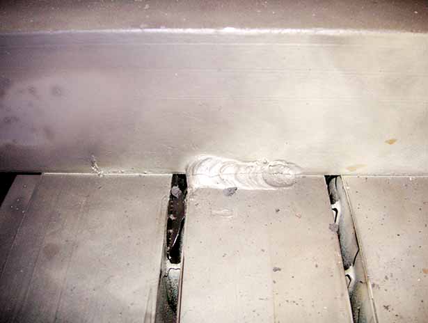
Figure 14: Fractured Stator Welds
The fracture cited in Figure 14 is prevalent in all welds between the stator frame and stator core.

Figure 15: Cooling Tube Contamination
Figure 15 identifies the contamination blocking the cooling tubes in the top of the electric motor. This cooling issue most likely accelerated the failure of the motor winding as shown in the darker winding spots as shown in Figure 12. This material is loose and can be removed easily by hand.
General Operating Conditions
The general operating area for these motors involves high temperatures, within the rating of the motor ambient temperature, and doors accessing the motor area above the reheat ovens were damaged in the open position, allowing contamination at the motors. There is no filtering systems involved with the electric motors or their cooling systems.
Financial Impact of Motor Failure
The failure of the combustion fan, while tube repairs were being performed on a separate combustion system, resulted in a loss of two turns. At 1,000 tons per turn (shift) and $550 per ton, a loss of $1.1 million occurred (numbers are not accurate for the present day).
With all four motors, including the spare, showing coil movement, and several of the motors not having been cleaned in up to five years. Although we could not substantiate the frequency of cleaning, or lack of it, due to the condition of the CMMS data. This would indicate the possibility of additional failures in the near future and motor life expectancies substantially less than the expected 15-20 years.
Maintenance Recommendations
Some of the critical issues related to these motors included:
- Cleanliness, blocking and contamination of motor cooling system.
- Oil leaks into the electric motor through the bearings and pressurized oil system.
- Manufacturing issues, such as poor welds and loose coil ends.
The chain of events leading up to the final motor failure is unclear, resulting in an RCFA that was substantially incomplete. However, by removing as many of the issues as possible, the owner will increase the reliability of the electric motor.
The basic maintenance requirements are based upon:
- Cleanliness of the cooling system; and,
- Prevent oil leakage into the electric motor.
The issues related to loose coil ends and poor welds would have to be repaired through rewind repair, possibly following motor failure. In the meantime, the failures are expected to primarily be to ground as the coil leaves the slot.
The following are the recommendations for additional maintenance of these electric motors:
- Cleanliness:
- Periodic cleaning of fans and cooling tubes, at least quarterly.
- Install a filter system to prevent contamination from entering the motor cooling system and schedule periodic cleaning/replacement of the filter medium.
- Monthly visual inspection of the motor cooling system and cleaning based upon condition; and/or,
- Repair doors to the motor area to prevent contamination from entering the motor cooling system.
- Oil Leakage into Motor:
- Periodic inspection of the interior of the motor to see if there is oil in the bottom of the stator housing; or,
- Quarterly motor circuit analysis (de-energized winding test) to determine if contamination affects the winding.
- Evaluation of the condition of the motor windings:
- Electrical Signature Analysis to monitor winding mechanical movement; and
- Motor Circuit Analysis to monitor winding insulation system condition.
Key Findings and Actionable Takeaways
A steel plant combustion fan failed following 7-8 years of operation. An electric motor life of 15 to 20 years can be expected of this type of motor in this environment. During a post-mortem inspection of the electric motor, it was determined that excessive oil contamination, coil end-turn movement, and blocked cooling tubes contributed to the failure.
The remaining motors, including the spare electric motor, each showed some of the signs that would lead to premature failure of the electric motors.
The recommended maintenance that can improve the reliability of these machines includes repairing the doors to the motor area, installing a filter system, a visual inspection of the cleanliness of the fans and cooling system, inspecting oil leaking into the motor, and a combination of motor circuit analysis and electrical signature analysis. This is in addition to other maintenance practices such as fan cleaning, bearing lubrication, etc.