
A tremendous amount of time, productivity, and production can be lost using improper troubleshooting and evaluation techniques. In this article, we will provide examples of ineffective traditional troubleshooting, sometimes referred to as ‘root-cause,’ and effective forensic analysis of machines using PROACT® Root-Cause-Failure-Analysis (RCFA) techniques.
Why Traditional Root Cause Analysis Falls Short
A common misconception of Root-Cause-Failure-Analysis (RCFA) or Root-Cause-Analysis (RCA) in the service industry is that the obvious issue, or visible fault, is the root. For instance, an electric motor fails in operation and is sent in for repair; the service center disassembles the unit and sees that the winding is shorted.
As a result, the reported root cause is a shorted winding. However, the information obtained is rarely the actual root. Digging deeper and continuing to ask questions, identifying the context of operation, and reviewing the failure evidence, the actual cause of failure is rarely the obvious point of breakdown.
The visible fault is rarely the true cause of machine failure.
In fact, seldom is there just one root cause; failure is often the result of many factors working in tandem. In this article, we will discuss a hybrid method of RCFA referred to as forensics, or the ‘CSI’ of system or component failure.
The process of forensics comes into play regardless of the amount of information available to the investigator and utilizes the resources required to provide a conclusion. The process can be broken down into several simple steps:
- Preserve evidence surrounding the conditions being investigated;
- Determine the limits of the investigation, if any;
- Determine who should be involved and at what level;
- Analysis of conditions (fault tree) and verification;
- Reporting, and
- Follow-up.
It is important to review all possibilities during the process. It is human nature to jump to conclusions based on past experiences and bypass logical evidence. The process requires the forensic analyst to step back and take a broader view, understanding that the point of failure is often a weakness or fuse in the system.
The Role of Tools and Verification in Forensic RCFA
Adapting tools and software where they are useful and effective throughout the process is helpful. For example, in this article, we will utilize PROACT®, which provides a method for tracking the forensic process and managing evidence. Other software systems can be just as useful and should be selected based on the investigators’ needs and experience.
One step to successfully applying forensic analysis is verifying information that may not appear relevant.
In forensics, irrelevant details often hold the real answers.
In numerous cases, a factor considered irrelevant has been a primary driver of the issue. In other cases, it may indicate an unrealized problem. In all cases, verbal input and opinions must not be mistaken for fact or as evidence to prove or disprove a hypothesis.
A key component of any failure is the failure chain. Seven to eleven things must go wrong for a catastrophic failure to occur. These may include latent equipment faults, training, specifications, design, application, or other issues that work independently or as a group.
Forensics allows the investigator to identify the ‘chain of bad’ and strengthen, change, eliminate, or redesign links to correct the issue. In effect, you must ‘break the chain of bad’ to reduce or eliminate the failure in the future.
Case Studies: Real-World Forensic Investigations
Case 1: Wind Generator Insulation Systems
The investigation was initiated because generator insulation systems were failing alarmingly across several wind farms on machines in place for less than five years.
The high failure rate was partially hidden in the past because of an even higher rate of failure of the wind turbine blades and gearbox bearings. While the blades continue to have a high failure rate due to environmental conditions, the chain of bearing failures in the gearboxes has significantly changed.
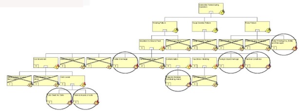
Figure 1: Failure Analysis of Wind Generator
A series of inspections on machine failures by repair organizations noted that magnetic wedges had been ejected into the air gap of the machines. This caused the organizations to publish information related to magnetic wedge failure, that the loose wedges somehow became jammed into the insulation system or were vibrating against the insulation system until it failed.
Overall, this did not make sense as some machine designs had this issue while others, also with magnetic wedges, did not fail within the same period.
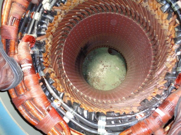
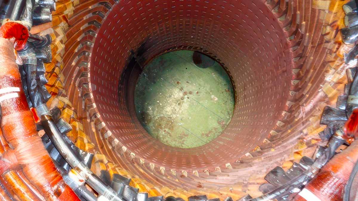
Figure 2: Failed Generator Winding
The initial hypothesis was investigated from when the machine was received through disassembly. As part of this, the machine was stripped using a special low-temperature stripping process that allowed investigators to remove intact insulation systems.
The first thing that was noted was that the coils in the stator were relatively loose, and significant abrasion had occurred. Samples of the coils from the stator were taken from around the failed area and areas that were in good condition, investigated by peeling back the layers, and evaluated using a small handheld digital microscope.
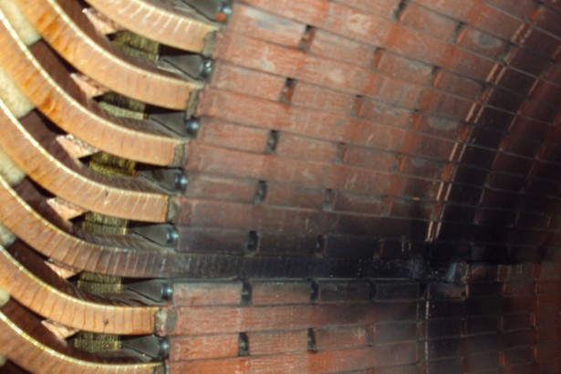
Figure 3: Missing Wedge in Generator Winding
As the analysis and evaluation of the hypothesis progressed, it was noted that the coils were smaller than the standard size for the slots. This was due to a combination of two factors: the coils had been made undersized, and insulation material shrinkage.
The coils were being held in place by epoxy varnish, which had released the coils due to thermal shock (significant and constantly changing temperatures).
All failures were found to have occurred at the top edge of the coil where there was no wedge, and in the direction of rotation. In the area that had not failed to ground, there was magnetic material which appeared to be iron dust from the magnetic wedges.
Other defects in the materials allowed for movement, including using low-grade insulating materials and the compactable packing materials under the wedges. This is of concern because, while the generator is operating, the coils move radially in towards and out away from the rotor at twice the line frequency as the fields expand and collapse. The force varies based on the generator’s loading.
Field testing with Electrical Signature Analysis (ESA) verified that the coils are moving during operation. The problem was identified, and removal and inspection of the generator confirmed the finding.
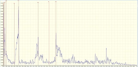
Figure 4: ESA Analysis of Generator in Place
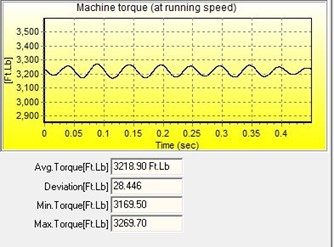
Figure 5: Torque Ripple of Generator in Operation
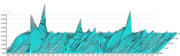
Figure 6: Waterfall Analysis of Generator
The result of the findings and confirmation was to look at methods of tightening the coils in the slot. Fewer tape layers would be used for coils with thicker walls, and ripple springs would be installed.
The ripple springs would allow expansion and contraction of materials without allowing loosening of the coils. In other cases, the coils are made tighter in the slots. Tighter and stiffer materials are used, and the varnishing method uses a thicker VPI varnish.
Case 2: Breaking Shafts on Variable Frequency Drive Application
Multiple motors failed in an application with a shaft-mounted fan and variable-frequency drive. Differences of opinion occurred early on, which resulted in changing out multiple motors of different sizes, altering the machine’s operation, and providing misleading and incorrect information between organizations.
In fact, the various companies involved were deliberately segregated and prevented from communicating. The problem of shaft breakage and catastrophic equipment failure proceeded through three 800 horsepower, 3600 RPM and 600 horsepower, 3600 RPM electric motors with varying loads and speeds.
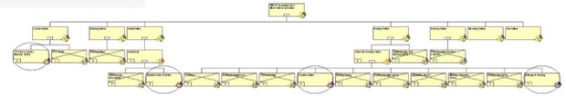
Figure 7: Failure Analysis of VFD Motor
Over two years after the start of the application and problems, the companies were forced together, and a forensic analysis was performed. In addition to the testing, Electrical Signature Analysis was also applied to confirm several specific issues.
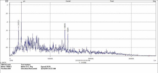
Figure 8: Vibration Signature in Acceleration
During the analysis, a number of questions were asked and compared to previous written and emailed responses and reports. Key was the very original request by a field vibration analyst who noted that specific vibration signatures he related to VFD application in acceleration were excessive. He had asked if the drive had been auto-tuned to the motor.
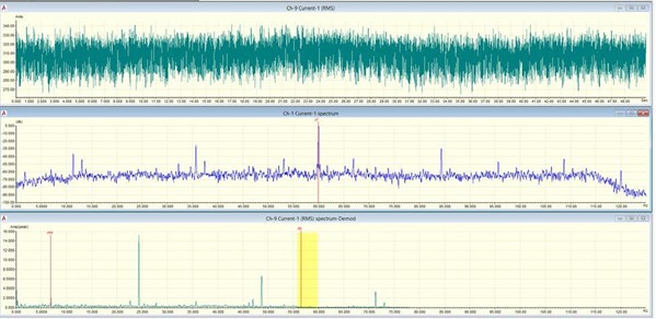
Figure 9: ESA of Torque Ripple
Before confirmation data could be taken with ESA, the equipment was auto-tuned. Afterwards, the ESA torque ripple data was taken and found to be still high, and directly related to the information detected with vibration.
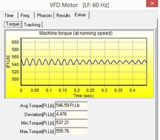
Figure 10: Torque Ripple of Motor on VFD
Once the fault was identified, additional work was performed to determine if the existing torsional vibration (torque ripple) could be further reduced. This included operating the equipment across various loads and operating speeds, as well as comparing the data.
The findings resulted in instructions being put in place by the end user, manufacturer, and other participants to ensure that auto-tuning would be performed in the future. Additionally, it was determined that the application of ESA would be utilized earlier during failure analysis.
Case 3: Lubrication Issue from Leaking Seals
A series of small, one-horsepower critical motors mounted on gearboxes were repaired to original specifications. Upon returning to service, they all started leaking oil from the gearbox into the motors. Because of the specific end user, the motors were evaluated using forensic techniques.
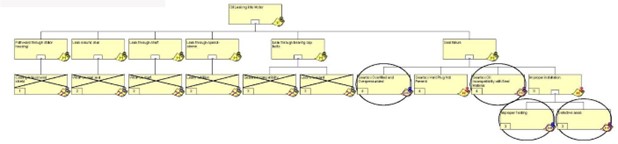
Figure 11: Failure Analysis of Stator Seal
This technique calls for pursuing both obvious and not-so-obvious conditions. In this case, it was noted that the seals were sticky, malformed, and cracked.
This brought about the modification required in the specification, in which a special seal is applied to the shaft to protect against the gouging of the seal into the shaft. It was found that on some units, the seal ‘rolled’ because of the larger diameter, resulting in the lip facing outward and reducing the seal.
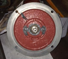
Figure 12: Motor Drive End with Seal
A simple question was asked, partially based upon the ‘stickiness’ of the Viton® seal material that had been specified. The oil was Mobil SHC 626, which was then checked against the materials chart.
Viton was selected because it is generally resistant to most materials and has a broad temperature range. Upon evaluation of the material compatibility chart, it was found that most Buna® and Viton materials were specifically NOT compatible with the oil. There were only a handful of materials that could be used.
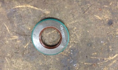
Figure 13: Failed Seal
The finding immediately spurred a series of meetings to discuss Viton material changes throughout the rest of the equipment. It was discovered that the other components were also having problems.
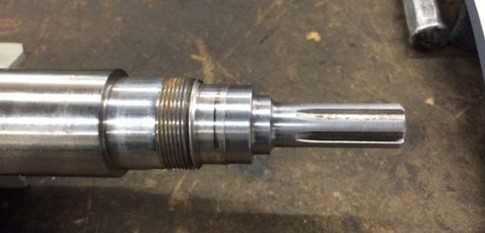
Figure 14: Shaft Seal Surface
The result was that a material was selected that could be applied as a seal and gasket. Shaft repair changes were implemented, including turning the shaft and using a sleeve.
Key Takeaways for Applying Forensic Analysis
Forensic analysis can be performed quickly to avoid repetitive equipment failures and to identify the cause of failures for other improvements. A fully implemented forensic analysis, which runs parallel to root-cause failure analysis, can also identify potential problems or uncover the unexpected.
A simple fact must be considered during any analysis: human input can be considered for investigation, but must never be used as a factual basis for conclusion.
Facts, not opinions, drive true forensic conclusions.
In most cases, the reason is that people will think something has occurred a certain way because of their past experiences. Sometimes, the reason is an attempt at deception for whatever reason.
A variety of tools are often used to confirm the analysis’s findings. These tools may include technology such as vibration analysis and ESA, or others, such as visual inspections. Whatever is selected must provide factual, measurable, or comparable data.