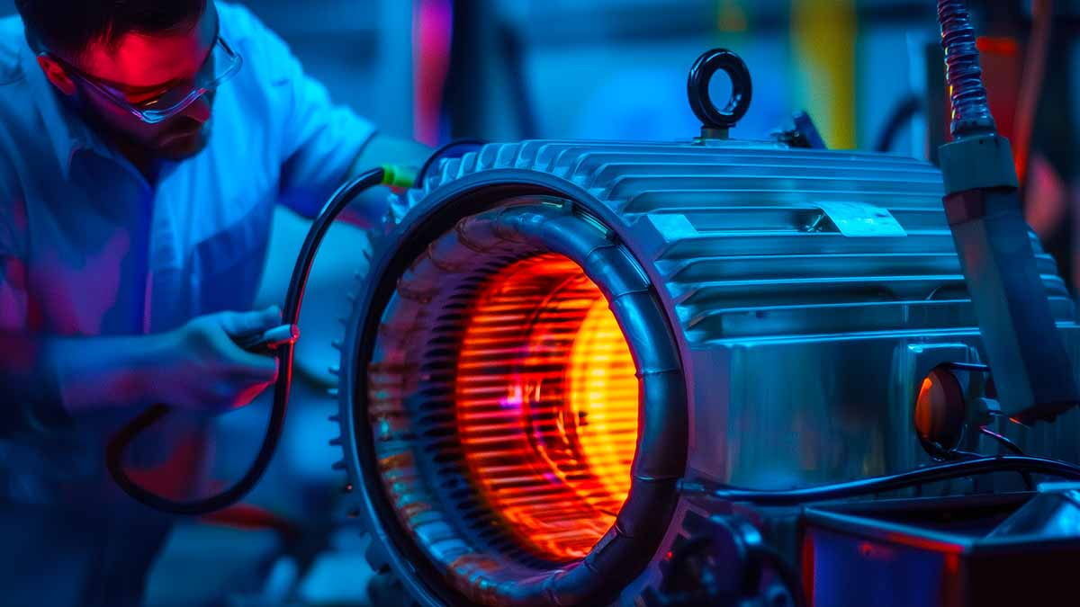

In some cases, diagnosing high shaft currents in electric machines requires additional testing. In a small motor-conveyor application, frequent bearing failures were traced to excessive shaft currents.
The motor, connected via a synchronous belt to a gearbox and chain system, measured 60 volts from the shaft to ground. However, due to the sensitive location, images of the machine and VFD are unavailable.
The motor owner had doubled up on drive output passive inductive filters based on vendor sales recommendations. The result was little to no improvement in the shaft currents and continued failure. The first test was performed with an EMPATH electrical signature analyzer (Figures 1 and 2).
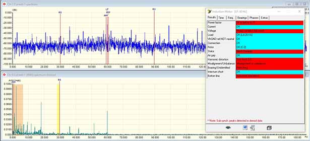
Figure 1. Inverter findings with Electrical Signature Analysis (ESA) testing.
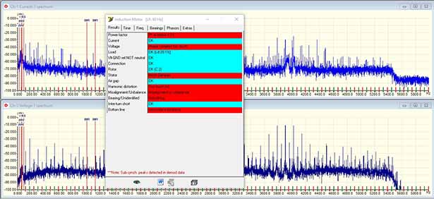
Figure 2: High-frequency data set showing stator mechanical and 4kHz carrier frequency.
Identifying Shaft Current Issues in Motor Bearings
At the drive’s output between the filters and the motor, tremendous noise continued to be present. In particular, constant power harmonics, winding degradation, bearing defects, and additional issues were present in both voltage and current.
Doubling up on drive output filters didn’t solve the issue—shaft currents persisted, leading to repeated motor bearing failures.
A set of tests was performed with an EMPOWER motor current signature analyzer in order to test the inverter, ground lead in the cabinet to the motor, and the current clamp was placed against the side of the motor frame for an additional understanding as to where the currents were present.
This was performed because the ground conductor was passed through the same conduit as the output leads from the inverter, which was also individual conductors, and no motor to local ground conductor was present.
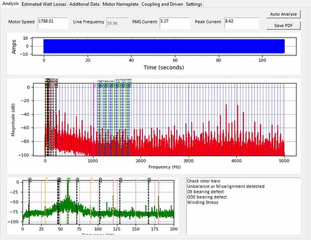
Figure 3: Evaluation of the winding using the EMPOWER MCSA system at the output of the drive filters.
Of note is that the speed varies slightly between data collection. Also, the current reads high with the Motor Current Signature Analysis (MCSA) versus Electrical Signature Analysis (ESA) due to the type of RMS data collection and average across the 120 seconds.
Figure 4 shows the harmonics to 22kHz in decibels (relative force to the primary frequency) in which there are multiple harmonics (odd, even, and inter) to approximately 20+ kHz. The very high frequencies will induce across the loose conductors into phases and ground.
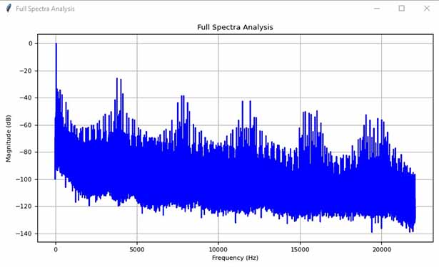
Figure 4: Decibel harmonics of carrier frequency with even, odd, and inter-harmonics.
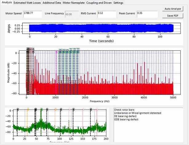
Figure 5: Ground test with MCSA at VFD main ground which includes ground lead from motor.
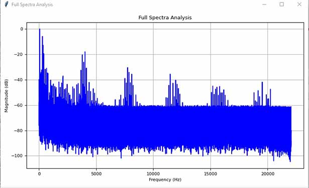
Figure 6: Ground lead harmonics. Note that they are similar to the power current harmonics.
Harmonic Distortions and Grounding Problems in Motor Failures
Figures 5 and 6 show current taken at the main ground at the variable frequency drive. This ground is used as a reference for the VFD and the ground for the electric motor. This should not be showing these harmonic frequencies and represents that the leads running through the conduit have power currents induced into them as the leads and ground leads are running in parallel and are not balanced.
Parallel routing of power and ground conductors caused induced currents, leading to unexpected harmonic distortions and bearing damage.
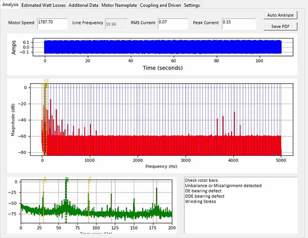
Figure 7: The signature picked up when the current clamp is held in parallel against the side of the electric motor. This value should not exist.
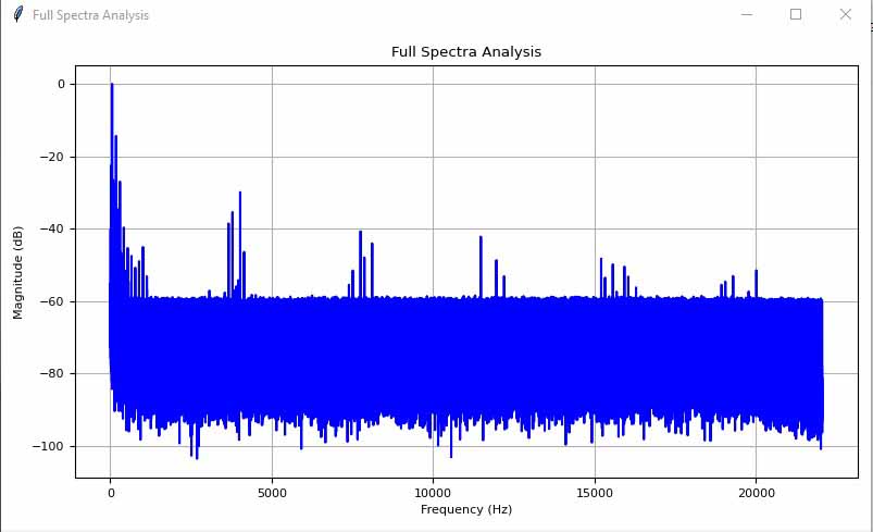
Figure 8: Induced current into the current clamp held in parallel and against the stator frame.
The defects are multifold and distracting, with a relatively simple solution that we have observed more often than not. If you are not pulling an inverter-rated cable between the VFD and motor that has shielding, a low impedance path, and a balance with the ground lead(s), then you will have to pass the ground lead outside the conduit.
If you review most VFD manuals, you will find that control conductors, incoming power and output leads, and ground leads that are not separated by some distance based upon the amount of current must pass each other perpendicularly and not in parallel to avoid induced currents and equipment failure.
The conduit itself will also have to be grounding at one end, the other, or both, depending on the distances. So, the solution in this case from the beginning would have simply been to remove the ground lead from the motor to the drive to outside the conduit – far less expensive than all of the investment into a small motor with no results.
Practical Solutions for Reducing Shaft Currents and Preventing Failures
The result of the ground lead in the conduit, which increases the potential for motor and drive failures, includes operational conditions with the drive, such as torsional and speed changes.
In addition, the induced voltage and current will also be present on the surface (ground) of the electric machine, which generates a potential between ground and the motor shaft and ground and the winding. This results in the rapid degradation of components in the electric motor, including winding defects.
A simple rerouting of the ground lead outside the conduit could have prevented repeated motor failures and costly downtime.
The additional tests shown in Figures 7 and 8 are performed with some form of coil against the stator frame. This is sometimes referred to as a ‘stray flux’ test, which is referred to in technical academic literature and some commercial systems as a reading of the stator magnetic field.
The frame of the machine should be considered part of a Faraday cage and must meet certain RF emissions to meet electromagnetic standards. As a result, it is very unlikely that you can induce flux current into a coil from the stator itself.
Instead, the value measured on the surface of an electric motor with a coil is from winding leakage currents and ground common-mode currents. These can be from an electric machine such as an isolated motor or a laboratory, but they can be noisy with ground noise issues or when a large number of inverters, lighting systems, or other ground noise conditions exist.
When conditions are right, the data can be similar but filtered and dampened from MCSA/ESA test results. How this works and can be used to evaluate winding condition is included in a paper published by this author in IEEE Summer 2025, in addition to several ongoing industry and utility studies. The misunderstanding is usually based upon a lack of understanding of electric machine design, standards, and operation.
Key Takeaways and Final Recommendations
In conclusion, we generally recommend that issues such as rapid degradation of machines be addressed by an experienced professional, not sales/marketing personnel.
While only 5 horsepower, this was a critical application in which sales of incorrect components from additional filters (one is recommended and would have sufficed) to shaft brushes and insulated bearings, none of which were effective, avoided the simple movement of a ground lead of approximately 3-4 meters to outside the conduit.
The challenge also provided the opportunity to demonstrate a new motor induction measurement method using a specific MCSA technology for winding and defect detection.