
The article ‘Partial Discharge Explained: Causes, Effects, and Prevention generated a few questions from companies and engineers associated with high-voltage partial discharge applications.
The article primarily focused on low-voltage electric machines (~230 volts and higher) with variable-frequency drives. From my perspective, the challenge involved misunderstanding specific conditions that affect partial discharge.
Understanding Partial Discharge in Low Voltage Motor Windings
This article will be a little more technical than most in order to help with that understanding. Part of the issue has been that many think the problem is related to ‘voltage spikes,’ which IEEE and IEC standards groups and researchers altered in the mid-1990s to partial discharge.
Partial discharge remains a frequent topic in peer-reviewed research. Studies focus on insulation methods to reduce the impact of frequency effects, which also affect high-voltage machines (> 6,000 Vac).
Key Equations for Partial Discharge and Insulation Breakdown
Partial discharge occurs when the local field intensity in a small void, air pocket, or defect inside the insulation system (dielectric) exceeds the breakdown strength of that localized region.
A commenter on the article mentioned above believed that this had to do with Paschen’s Law, a breakdown effect associated with the ionization of gasses (i.e., air) between one or more conductors. This is similar to partial discharge but not the same as it usually involves low-frequency concerns versus higher-frequency capacitive discharges.

The equation above describes Paschen’s law with Vb as the breakdown voltage, p as the pressure of the gas, d as the gap distance between electrodes, A and B as the constants that depend on the type of gas, and γ as the secondary electron emission coefficient which is dependent upon the material and gas composition. This results in a given minimum breakdown voltage at a specific product of pressure and gap distance.
Partial discharge is a localized dielectric breakdown in an insulation system under high voltage stress. In VFD applications, switching frequencies (2 kHz to 20 kHz) and fast voltage rise times (dV/dt) significantly impact partial discharge activity. High-frequency fields create intense localized fields, particularly in winding end-turns and reflected waves.
These conditions can double the supply voltage, increasing local field strength. This leads to surface discharges, known as corona (low-energy partial discharge), and repetitive partial discharge events. These accelerate insulation aging, further intensifying localized partial discharge.
If an insulation system contains a void or gap, the local electrical field in the gap is given in the equation below.
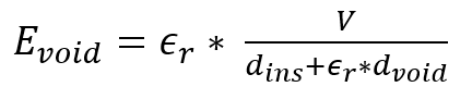
Where Evoid is the electric field inside the void, V is the applied voltage, ϵr is the relative permittivity of the insulation material, dins is the thickness of the insulation, and dvoid is the diameter of the void. A partial discharge will occur when Evoid exceeds the breakdown strength of the gas, as noted in Paschen’s Law.
The partial discharge inception voltage (PDIV) is the minimum voltage at which partial discharge activity begins inside insulation voids (equation below), in which PDIV is usually higher than the operating voltage.
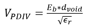
In standard low-voltage motors, PDIV is much higher than the operating voltage. However, high voltage, fast rise times, and high-frequency pulses create transients that exceed PDIV, triggering partial discharge at lower steady-state voltages.
When we add harmonic content, such as the high-order harmonics in VFD outputs without filters, the components add voltage stress and effectively reduce the effective PDIV. These harmonics modify the PDIV equation below.
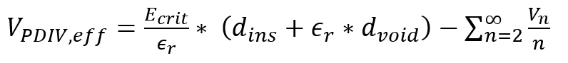
Where VPDIV,eff is the effective PDIV in the presence of harmonics, Vn is the voltage amplitude at the nth harmonic, with n being the harmonic order. Higher harmonics increase insulation stress, especially at frequencies above 1 kHz. At these levels, losses rise due to skin effect and dielectric heating.
When harmonics occur in the higher orders, as shown in Figure 1, the frequencies associated with VFD switching frequencies include multiples of those frequencies.
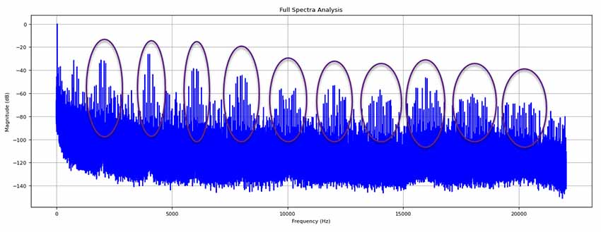
Figure 1: Harmonics and sidebands of the 2kHz switching frequencies in decibels.

Figure 2: Voltage and current waveform associated with Figure 1.
Each partial discharge event releases a small amount of energy, in which the impact gradually degrades the insulation system. The potential energy that is stored in a void is represented in the equation below.
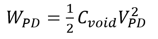
Where WPD is the energy released per partial discharge impulse, the Cvoid is the capacitance of the void, and VPD is the voltage across the void. For low-voltage VFD-driven motors, the energy released can accumulate over millions of cycles, leading to progressive insulation failure.
Standards and Best Practices for Mitigating Partial Discharge
While the above provides a basic overview of the technical side of low-voltage partial discharge in VFD electric motors, we should explore a few of the standards that cover this issue.
- NEMA MG-1:2022 Section 31.4.4.2 Voltage Spikes. This section also references IEC 60034-18-41 Clause 11 for partial discharge testing of an insulation system. The test is intended to be performed on representative samples when the stator winding insulation system is initially qualified and is not intended to require routine tests for each motor produced.
- IEC 60034-18-42, “Rotating Electric Machines – Part 18-42: Partial Discharge Resistant Electrical Insulation Systems (type II) Used in Rotating Electrical Machines Fed from Voltage Converters – qualification tests.”
- IEC/TS 61934, “Electrical Insulating Materials and Systems – Electrical measurement of partial discharges under short rise time and repetitive voltage impulses.
Understanding that these conditions can and will damage your electric machines on VFDs assists in avoiding the problem, such as using filters between the VFD and the motor.