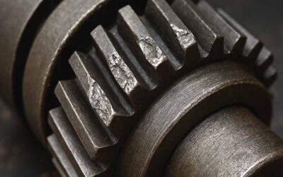
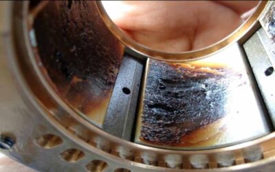
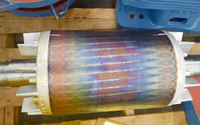
Numerous surveys conducted with industry in the United States have found that 70% of equipment failures are self-induced, and more than 30-50% of these self-induced failures are caused by maintenance personnel not knowing the basics of maintenance.
The other portions of these self-induced failures are caused by operator error, parts handling and storage, improper diagnosis of failures, inadequate or ineffective Preventive Maintenance programs, etc.
Over 90% of maintenance personnel fail fundamental skills assessments in key areas like alignment and lubrication.
This problem has been further proven through the skill assessment process I was involved with in the State of Georgia’s Skills Assessment program from 1990 – 1994, in which I was involved in the creation of the assessment.
This assessment program assessed the basic maintenance fundamentals through a written identification and performance format.
A high number of maintenance personnel in many different types of industries were assessed, and we found that over 90% of these personnel that were assessed in the “Basic Fundamentals of Mechanical Maintenance” scored 50% or less in the following areas:
- Belt Drives
- Chain Drives
- Bearing Maintenance
- Precision Measurement
- Lubrication
- Welding
- Couplings and Coupling Alignment
- Hydraulics and Pneumatics
A database has been compiled by the Technical Training Corporation (from 1993-2000) that has found similar results of their skill assessment program, but their database represents not only industrial plants in Georgia but also throughout North America.
These findings prove that the basics in maintenance are a fundamental problem in many maintenance organizations throughout the United States. One solution is to develop proper and detailed “Preventive Maintenance and Corrective Maintenance Procedures” and then train all personnel in how to use these procedures.
We will attempt to address some of the maintenance basics that a maintenance person must know to perform proper maintenance on a piece of equipment.
These areas are belt drive maintenance, chain drive maintenance, and coupling alignment.
Belt Drive Maintenance
Routine Preventive Maintenance is essential if a belt drive is to operate correctly. Belt maintenance should include regular belt condition checks, alignment, and tension. You should also perform frequent inspections of the sheaves and shafts.
Proper belt and chain maintenance isn’t just routine—it’s the difference between uptime and costly downtime.
Routine maintenance will extend the life of the sheaves and belts. Belt-drive maintenance requires little time, but it must be done regularly. Keeping the belts clean and free of oil and grease will help ensure a long belt life.
Proper tools must be selected. (These must be identified on your PM inspection checklist or Job Plan)
In addition to a set of basic hand tools, you will also need a reliable tension gauge with a set of belt tension tables, a set of sheave gauges, and a straight edge or string with a flashlight.
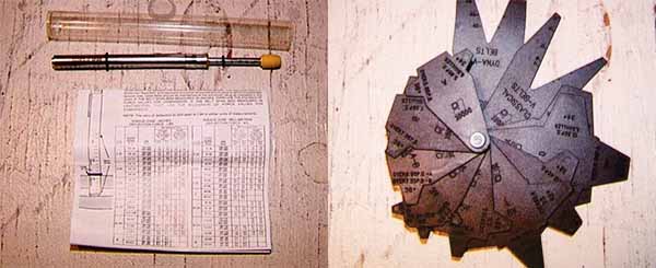
When the proper procedures are followed for installing V-Belts, they will yield years of trouble-free service.
Install the belt on the sheaves. Never force a belt on with a screwdriver, this can damage the belt and cause you to lose a finger. Next, begin increasing the distance between the sheaves by turning the jacking bolts; do this until the belt is snug but not tight.
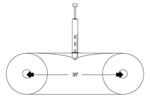
Using a belt tension gauge, tighten the belts to the manufacturer’s recommendation. Be sure to measure deflection and tension. This information can be found in a belt tension gauge’s information sheet.
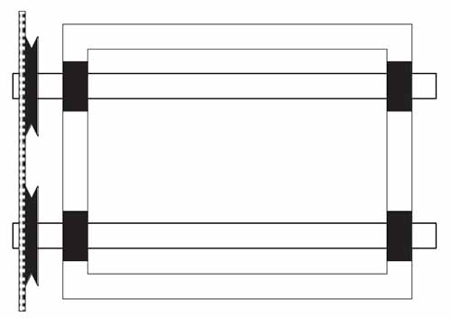
Check for parallel and angular alignment of sheaves. The tolerance for alignment of V-Belts is to within 1/10 of an inch per foot of span, and for positive-drive belts to within 1/16 of an inch per foot of span.
When you replace a belt, always check the tension immediately after installation. Check the tension again after 24 hours of operation.
The belt should never ride in the bottom of the sheave because the sheave is deeper than the belt. The belt is made to ride near the top of the sheave. The belt may wear to the point that it is riding on the bottom of the sheave. If so, it will slip no matter how much tension is applied to the belt.
Sometimes belts are stored on shelves in their original packaging. Other times, they are stacked without packaging. If possible, store them on two or more pegs to prevent distortion. Keep belts away from damp floors and high-heat areas.
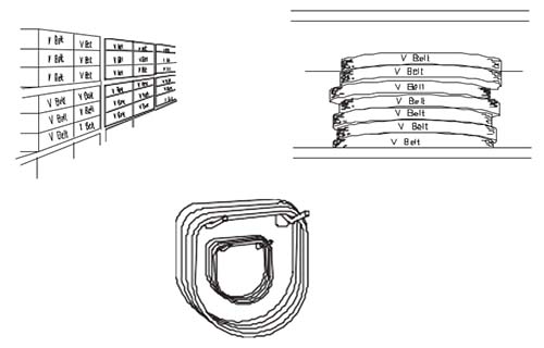
You may need to replace belts that are worn or damaged from overheating or contact with oil or grease. Never replace one belt of a multi-belt drive. Belts stretch with use. If you replace one belt of a multi-belt drive, it will be tighter than the others, thus not meeting the horsepower requirements the drive was designed for.
Chain Drive Maintenance
Chain drives transmit power between a drive unit and a driven unit. For example, if we have a gearbox and a contact roll on a conveyor, we need a way to transmit the power from the gearbox to the roll. This can be done quickly and efficiently with a chain drive unit.
Chain drives can consist of one or multiple strand chains, depending on the load that the unit must transmit. The chains need to be matched with the sprocket type, and they must be tight enough to prevent slippage.
An effective “Preventive Maintenance Program” will provide extended life to a chain drive system, and through proper “Corrective Maintenance Procedures,” we could prevent premature failures.
Preventive Maintenance
- Inspect a chain for wear by inspecting the links for worn
- Lubricate the chain with lightweight oil recommended by the chain
- Inspect sprockets for worn teeth and abnormal wear on the sides of the
- Realign sprockets using the same method used for belt
- Ensure the chain has the proper amount of sag (About ¼” per foot of span).
Corrective Maintenance
- Replace all sprockets and chain when replacing any portion of the chain drive. This ensures the chain drive operates under the pitch diameter. Worn sprockets have groves worn in them, which create changes to the pitch diameter. Worn or “stretched chains” change their pitch diameter by the chain wearing beyond limits, thus changing the distance between links. Sprockets and chains must match the pitch diameter, or they cause premature failure.
- If a chain is too long, do not install a half link without trying all means available to take up excess A half link does not have the load requirements of a full link and thus can cause premature failure.
Coupling Maintenance
Couplings are a vital part of drive systems. They are needed to transmit power from the motor or drive unit to provide work.
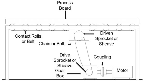
There are many types of couplings, each with a specific design and function. Knowing the correct coupling for an application is not enough. We also need to understand the proper way to install and align each.
When installed correctly, couplings can yield years of trouble-free service to any system. When they are not installed and aligned properly, downtime will result.
In this section, we will address the alignment of couplings. The alignment of a coupling can be performed using many different methods. We prefer laser alignment for proper alignment, speed and quality of the work performed. The straight-edge method or “eyeball” method should be considered unacceptable. Proper alignment has many benefits:
- Prevents premature failure of couplings, motor bearings, shaft seals on pumps and gearboxes, etc.
- Reduces energy cost. Improper alignment can increase the energy cost of a motor by 2-10%. Measure the savings by checking the amperage draw on a misaligned motor. Next measure the amperage draw on a motor properly aligned. Calculate the decrease in amperage and calculate your energy charge by your electric company, then perform the same task for all motors in your operation. The savings can be staggering.
We will not demonstrate the proper method for dial indicator coupling alignment. The basics apply to all methods of coupling alignment.
Before performing the alignment, we should always check the condition of the bearings. Set up a dial indicator with a magnetic base to read the face of the coupling. Push the shaft in and set the indicator to zero, then pull the shaft out and observe the reading on the indicator. Then, consult the bearing manufacturer for the allowable clearance. (Normally no more than a couple of thousandths.)
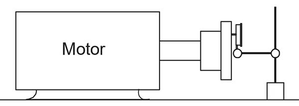
Checking End Play
Then set the indicator up to read at the top of the coupling. Push the shaft down and set indicator to zero. Then, pull the shaft up and observe the reading. Consult the bearing manufacturer’s guide for the allowable clearance. (Normally no more than a couple of thousandths.)
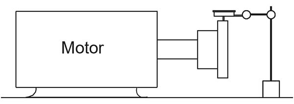
Checking Bearing Wear
Now check for run-out by placing the indicator on the top of the coupling. Set the indicator to zero and turn the coupling a complete turn. The alignment will only be as good as this reading is, so if the reading is excessive or more than about .002”, then move the indicator to the shaft. Maybe the shaft is bent rather than the coupling being bored off-center.
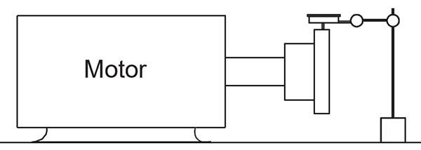
Checking Shaft/Coupling Run-out
Now, place the indicator so that it reads the face of the coupling, set the indicator to zero, and turn the coupling. If the reading is excessive then the coupling was not bored straight.
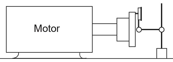
Checking Coupling Bore
Clean all mounting surfaces by removing rust or debris from the base. If this is not done, a soft foot can occur, and you will get a different reading every time you loosen and tighten a bolt.
Now position the drive and driven units so that the drive is slightly lower than the driven; in this example, we will use a pump and a motor. Use a straightedge to do a rough alignment. Do not spend much time doing this because you want to make the least amount of moves you can.
The indicator will speed up this process. Also, check the coupling manufacturer’s instruction sheet to ensure the couplings are the proper distance apart. Then, tighten all mounting bolts securely.

Check for soft foot by loosening one bolt at a time, then insert feeler gauges under each foot to determine the required shim thickness.
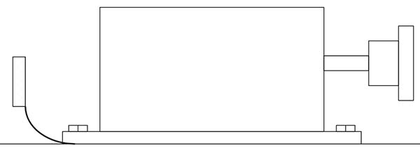
Mechanics often fear dial indicators because of their setup, and many feel that they are complicated and time-consuming. They are pretty simple and only take a little practice. Install the indicators so that they are set like the following pictures:
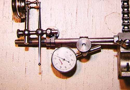
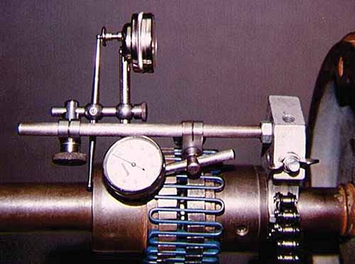
Now, let’s check the angular alignment from the side view. Place an indicator so the reading is taken on the face of the opposite coupling. Then, rotate the coupling so that the indicator is at the bottom. Set the indicator to “0” and rotate to the top. The indicator reading is the total gap difference. Use the following formula to calculate the required shim thickness:


Angular Side View
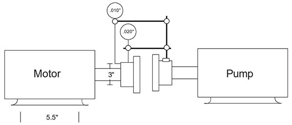
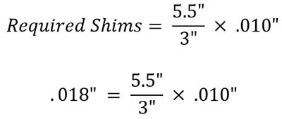
We know that when the indicator plunger is pushed in, it goes to the plus side. This means the top of the coupling is wider than the bottom, so we must shim the back two feet of the motor .018” to correct the angular alignment.

Parallel Side View
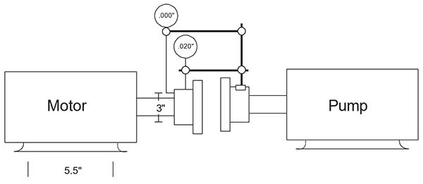
To check parallel alignment from the side view, place the indicator tip on the top of the opposite coupling. Rotate coupling to the bottom and “0” indicator. Then, rotate until the indicator is on the top.
The total shims required under all feet is half the total indicator reading. In the drawing below, the reading is plus .020”, so we need to remove .010” shims under all four of the motor feet.
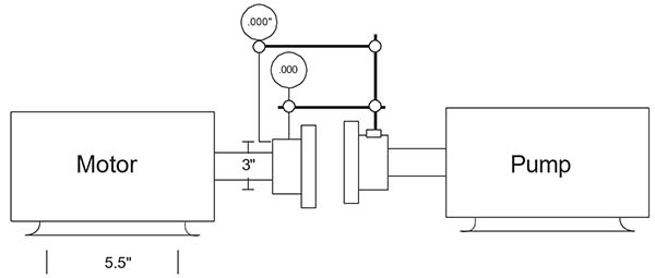
Now check angular alignment from the top view. Set up the indicator as you did when taking the other angular readings, then take the readings from one side to the other. Rotate the motor until the reading is “0”.
Check parallel alignment from the top view. Set up the indicator as you did when taking the other parallel readings, then take the readings from one side to the other. Rotate the motor until the reading is “0”. Now repeat the previous steps, and the alignment should be complete.
Remember that some equipment operates at extreme temperatures and the alignment must be adjusted. Consult with the equipment manufacturer for more details.
Maintenance Basics can cover many other areas. We have covered only a few. We hope this article has provided an awareness to anyone concerned about maintenance basics.
Ricky Smith, CMRP, CMRT is the Vice President of World Class Maintenance and a leading Maintenance Reliability Consultant with over 35 years of experience. He holds certifications such as Certified Maintenance and Reliability Professional (CMRP) and Certified Maintenance and Reliability Technician (CMRT). Ricky has worked with global companies like Coca-Cola, Honda, and Georgia Pacific, delivering expert maintenance solutions across 30 countries. His career began in the U.S. Army, advancing to leadership roles, including a position at the Pentagon as Facility Investigator for the Secretary of Defense. Ricky is also the co-author of Rules of Thumb for Maintenance and Reliability Engineers and Lean Maintenance: Reduce Costs, Improve Quality, and Increase Market Share.

